STATIC CAPITAL
Chris Wauchop Scale Models and Photography
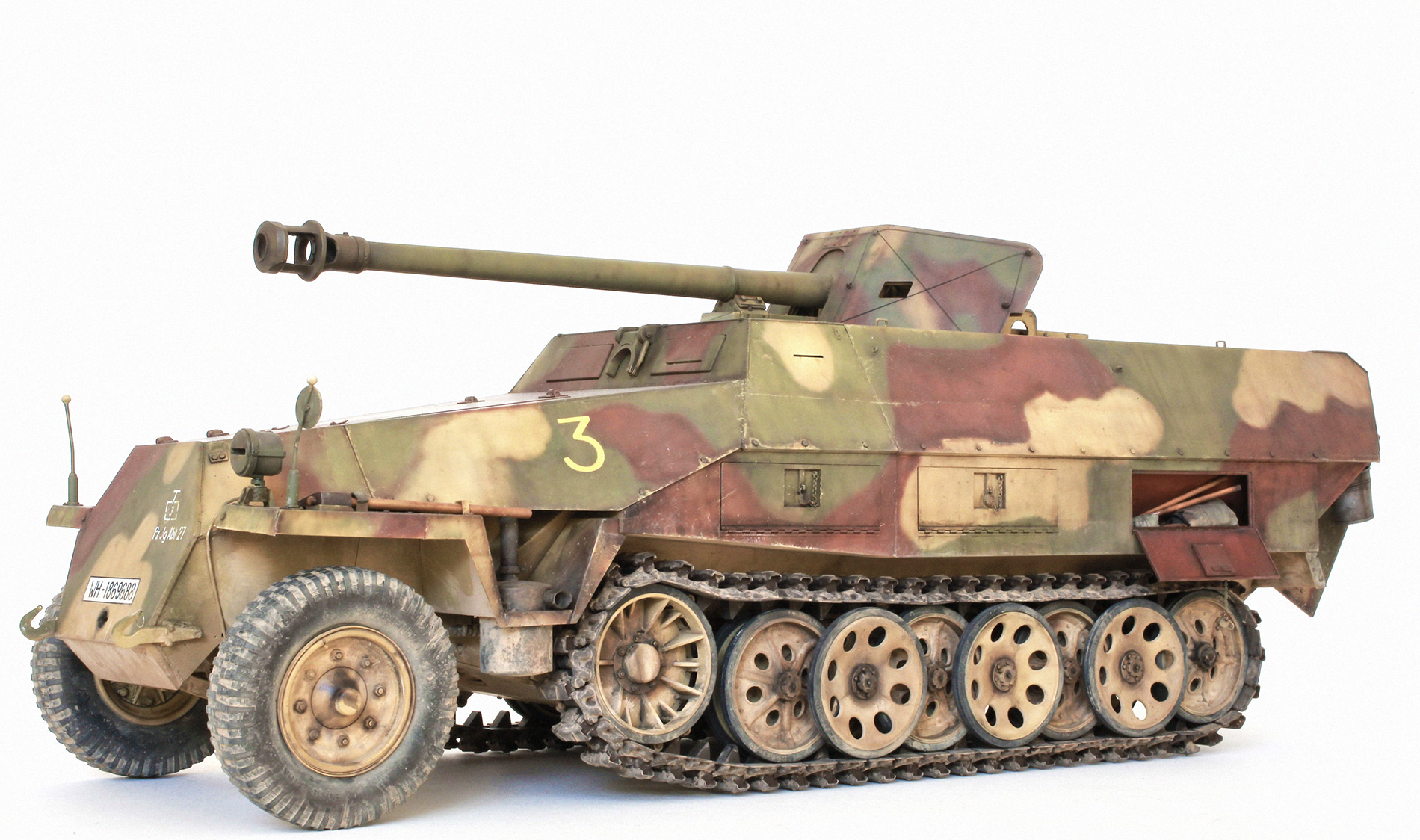
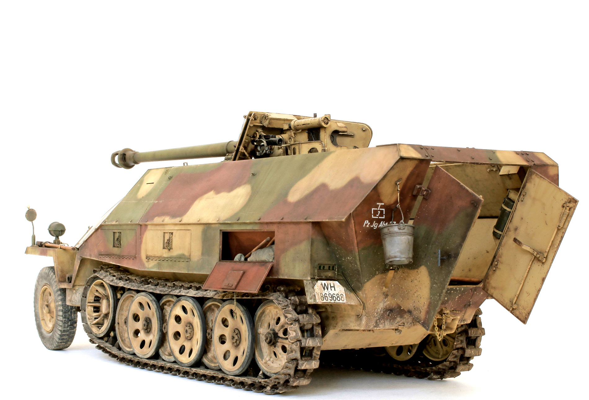
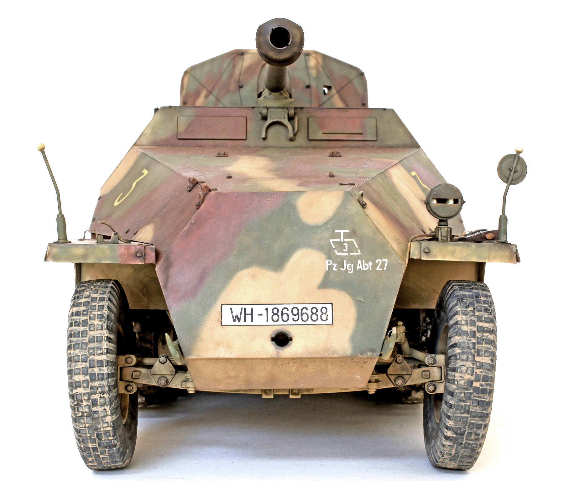
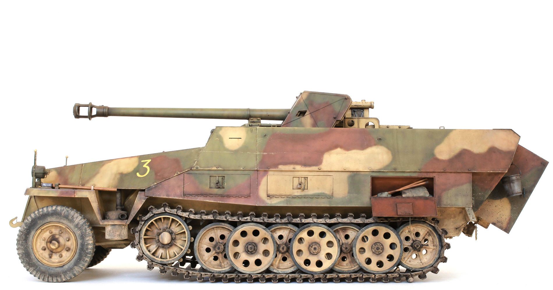
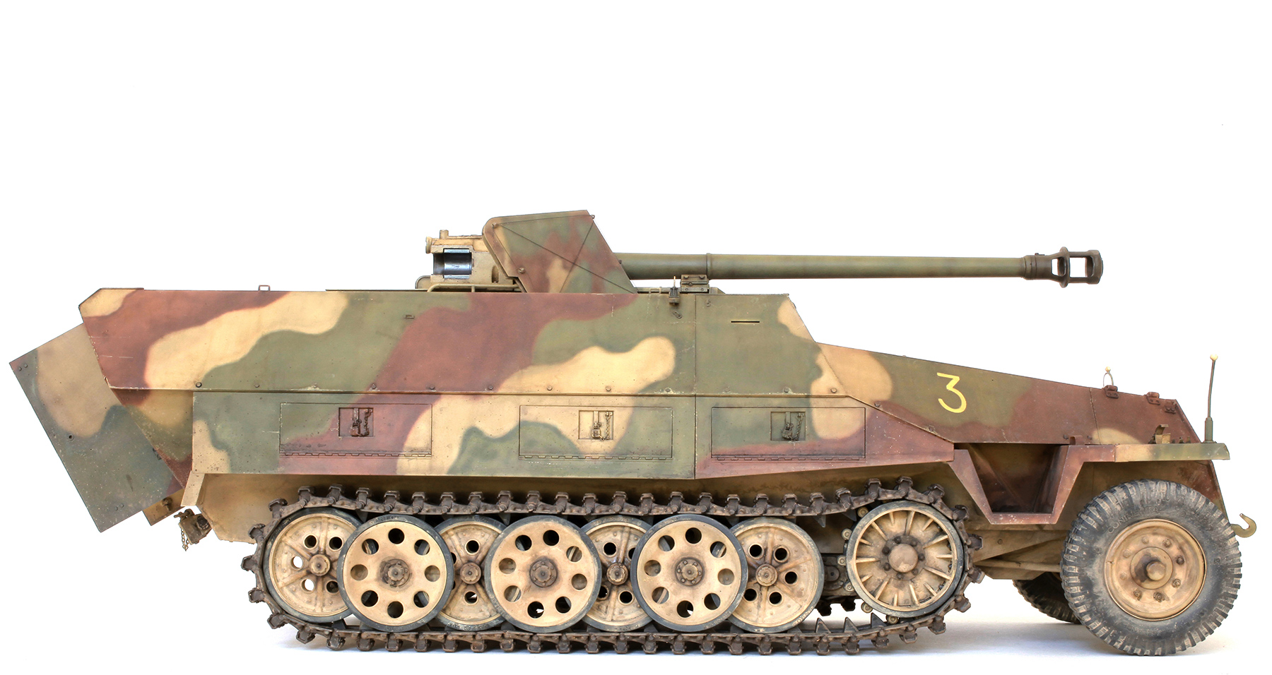
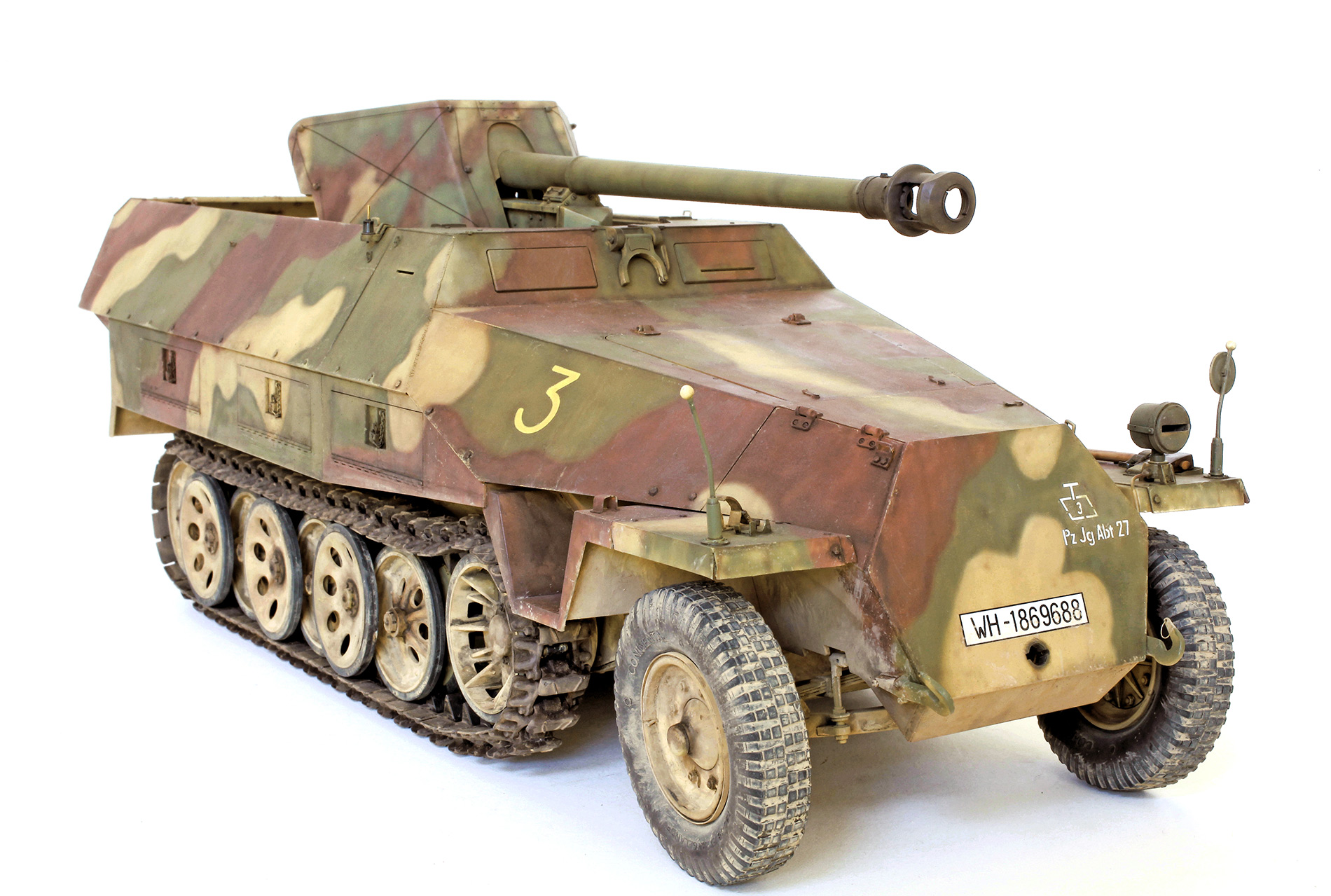
DAS WERK 1/16 Sd.Kfz. 251/22 ‘Pakwagen’
DAS WERK 1/16 Sd.Kfz. 251/22 ‘Pakwagen’
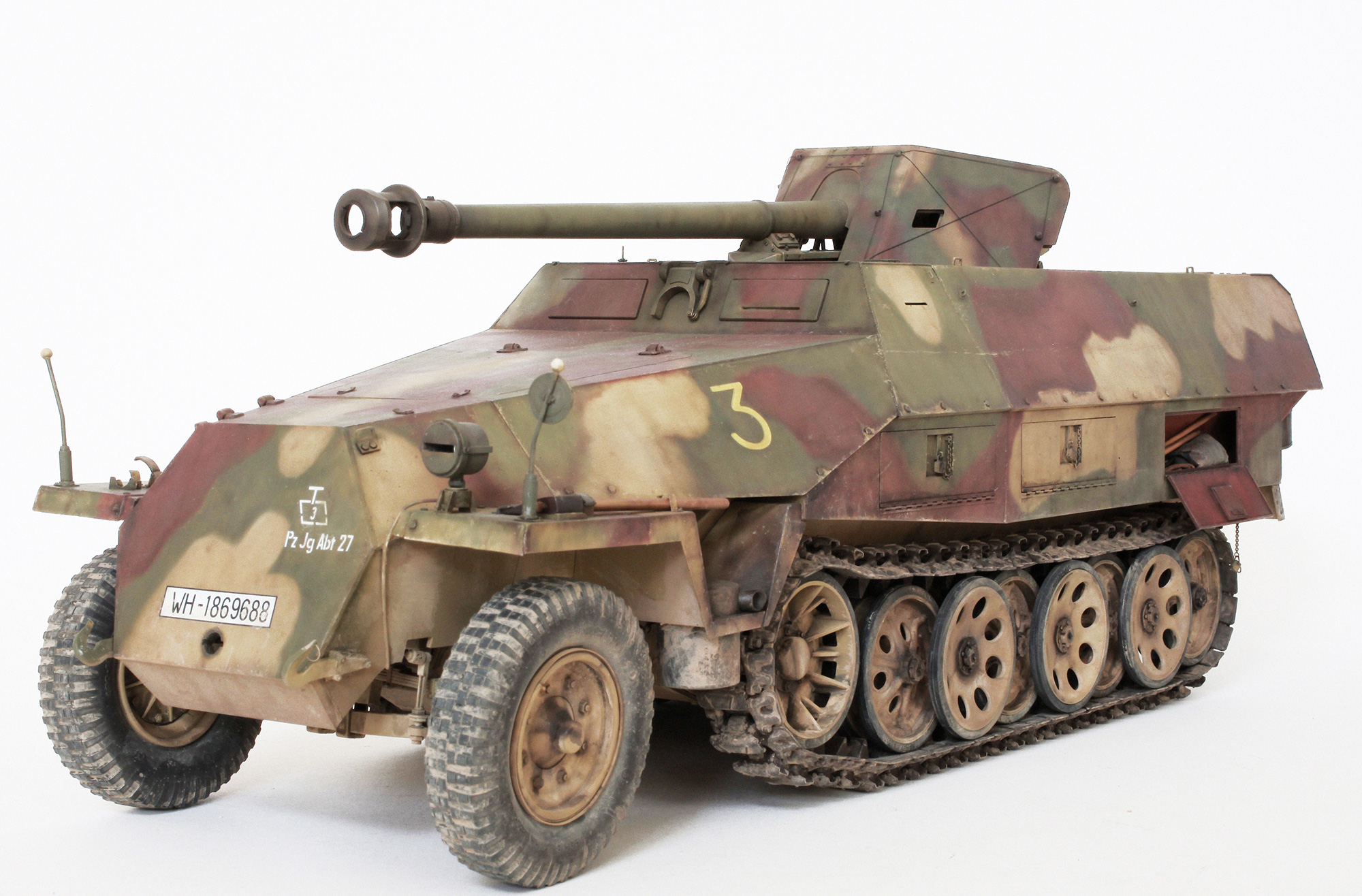
Sd.Kfz. 251/22 Ausf. D [Late] of 17.Pz.Jg.Abt.27, April 1945, Steinau/Oder, Lower Silesia.
I want to say from the start that this large kit may not be for the beginner. An impressive but ultimately inaccurate model may be achieved by building this kit straight out of the box but I don’t think a serious modeller would be totally satisfied with that result. I have spent at least six, very enjoyable months building this model and it has taken just about every ounce of the modelling skill that I possess to achieve the far from perfect result that you see here. Below you will see many photos of most, but not all of the changes and additions that I made. I am sure that the experts will spot many faults and omissions that they think need to be corrected and added. This does not detract in the slightest from the pleasure I derived from building this big model of probably my favourite AFV subject. I would highly recommend that any modeller interested in the subject give it a go and If you take your time I guarantee you won’t be disappointed.

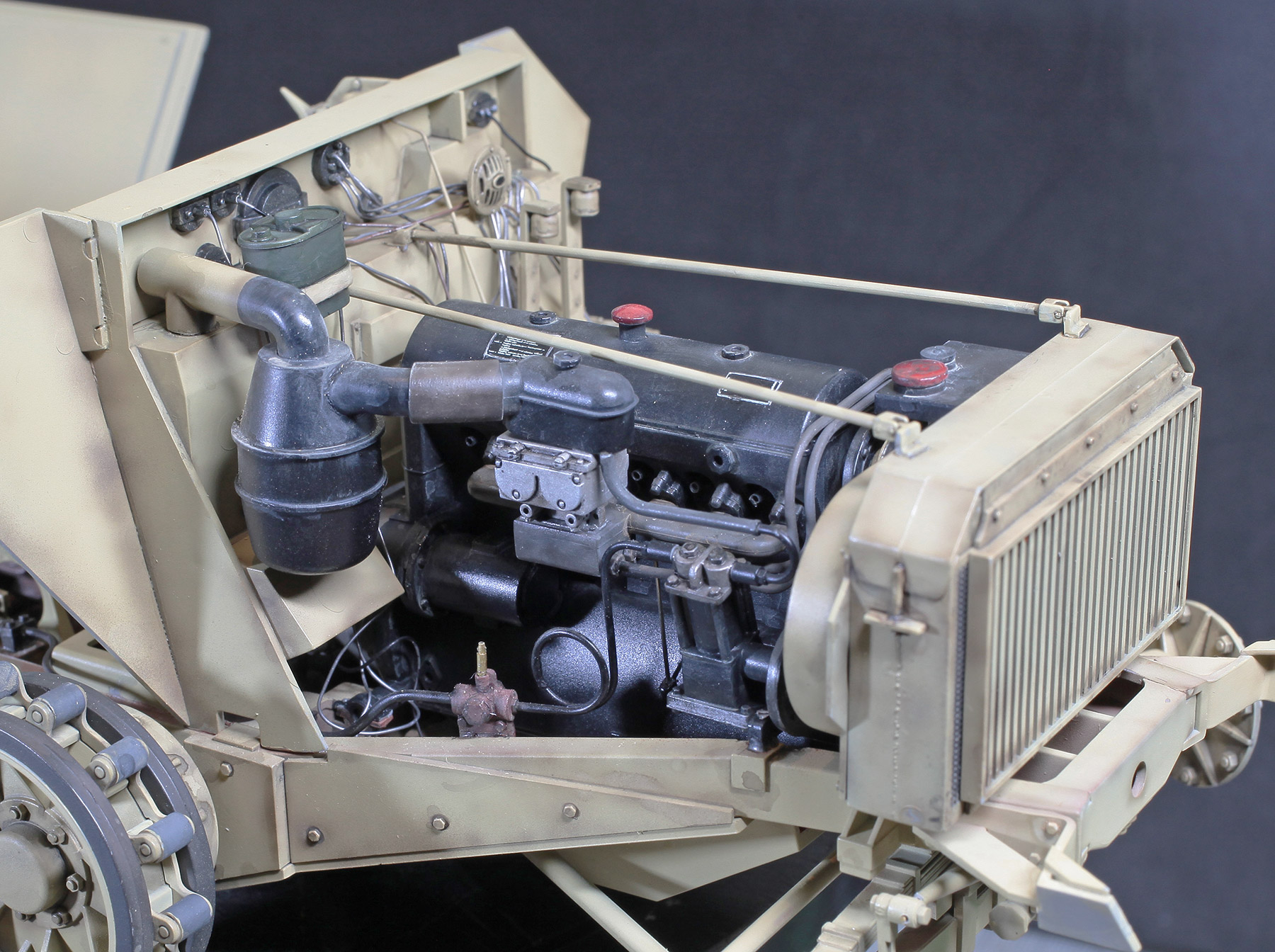
Engine and radiator drained of fluids and ready for installation.

Torsion bar and axle tubes installed and primed.
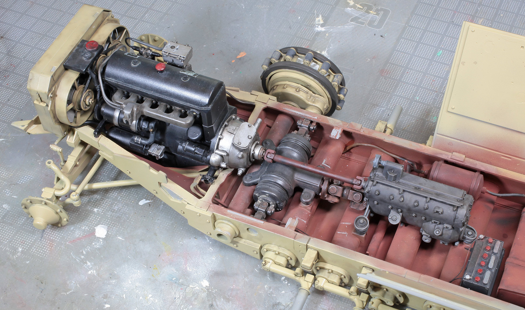
Radiator, engine, dif, gear box and battery.

From the other side.
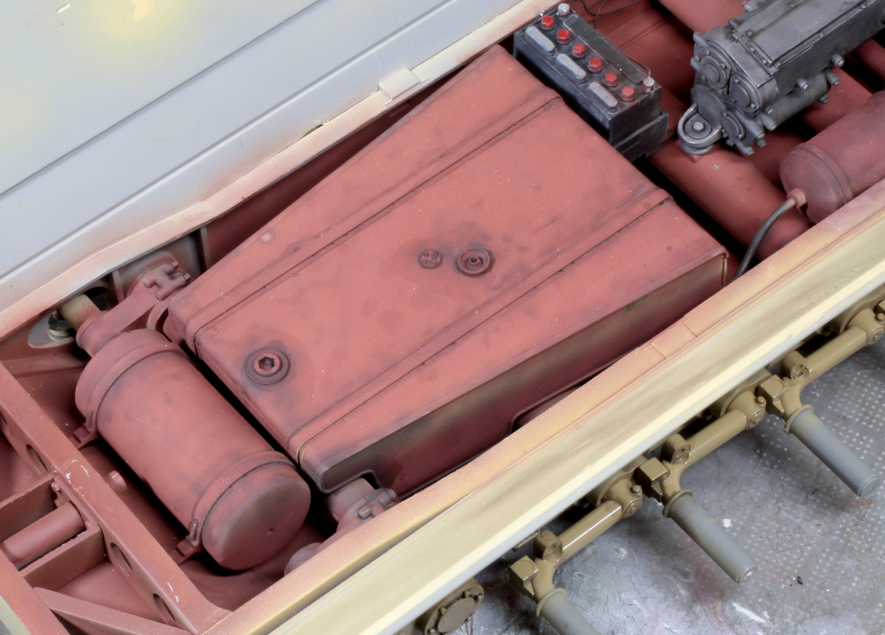
Fuel and oil tanks in, with a little grime added. None of this detail will ever be seen after the model is complete but I know it’s there and now so do you.
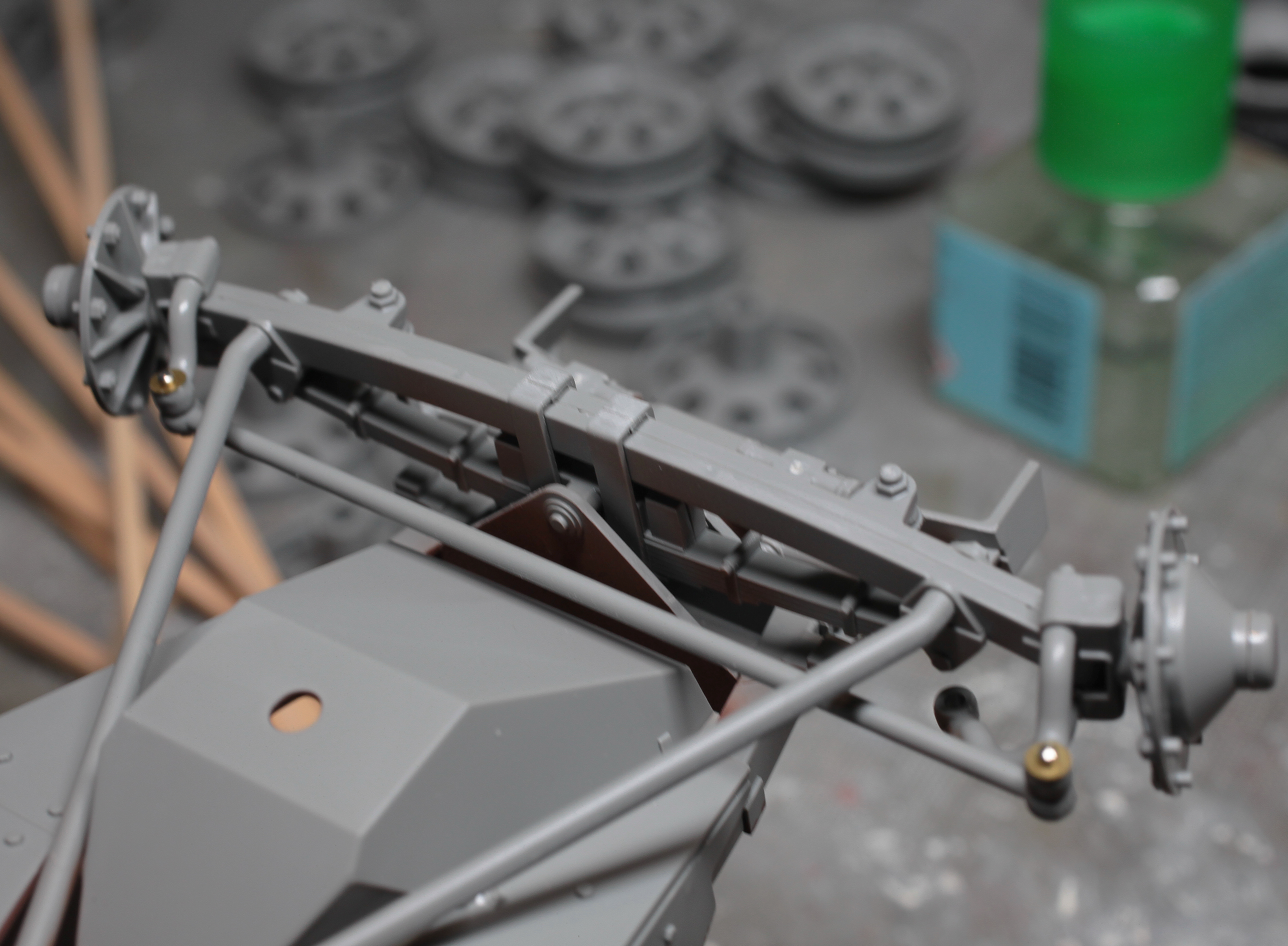
Front steering and suspension. Note brass washers and cut-down sewing pins used to enable front wheels to steer.
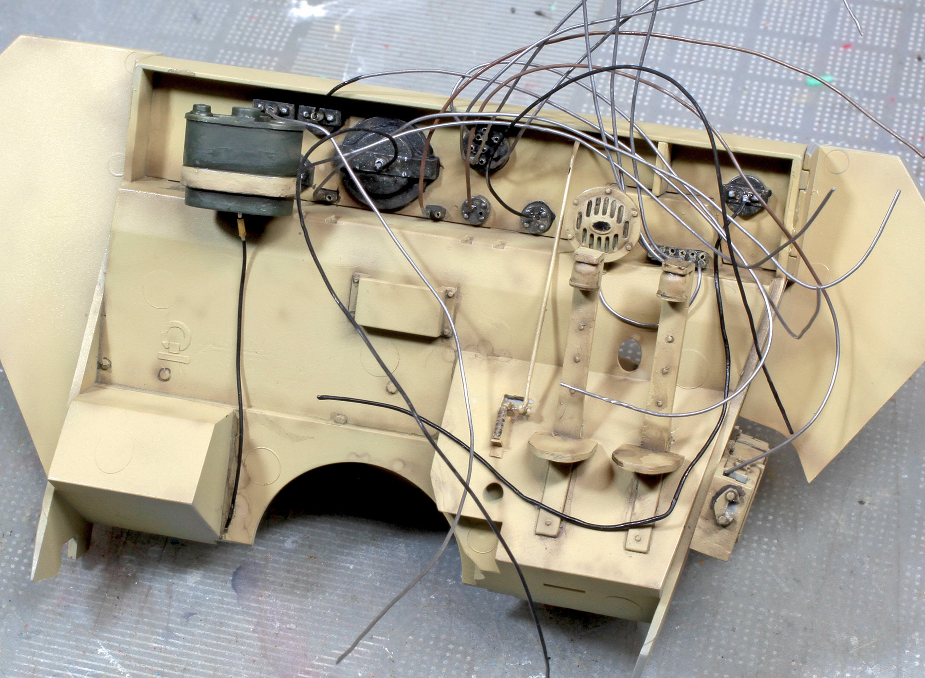
Wiring added to the back of the instrument bezels.

Dashboard instrument dials and various controls, levers and linkages.

Busy engine bay.
Other side.
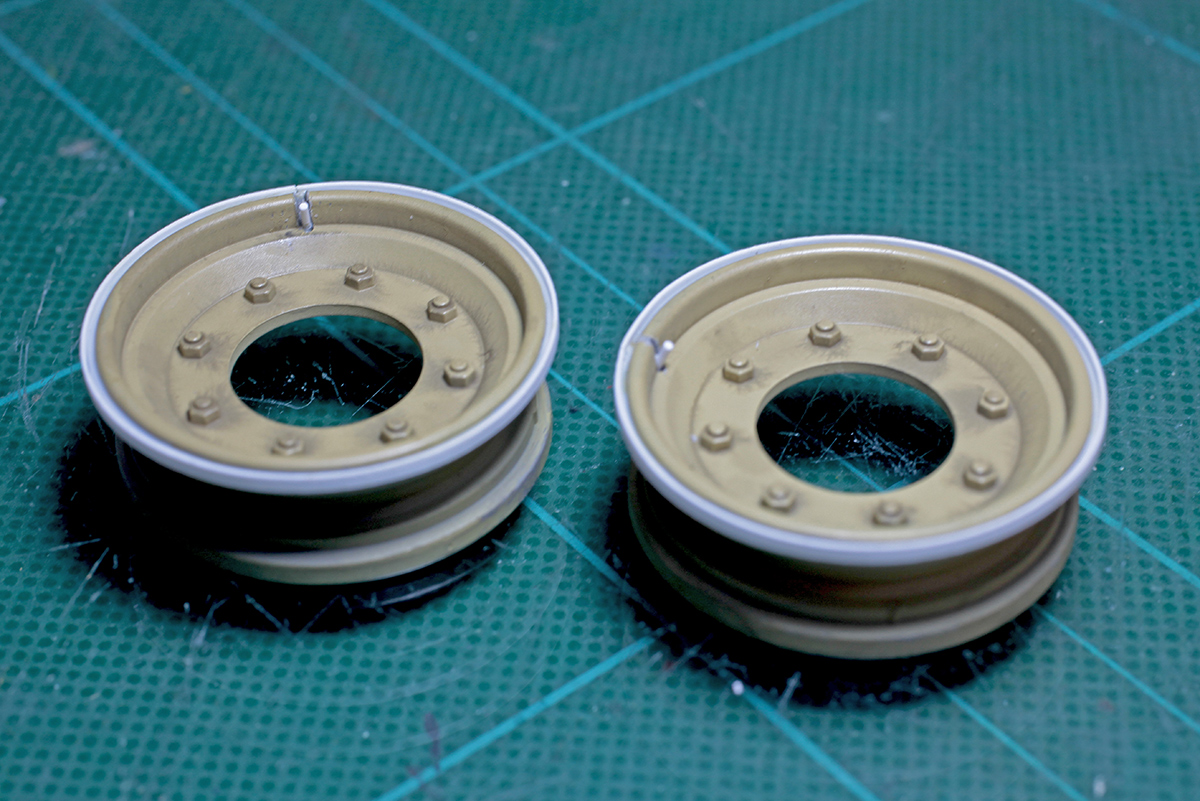
Extra detail was added to the front tyre rims using Evergreen plastic strip and rod.

A new engine bay hood was cut from 0.5 mm plastic sheet to replace the overly thick kit part. The kits moulded-on upper and lower hinge parts were drilled to accommodate hinge pins. The kit’s hood hinge parts were then very carefully removed and glued to the new part. The radiator cover was left as is but its hinges were drilled and both parts had new locking tabs added. Both covers can now be opened and closed.
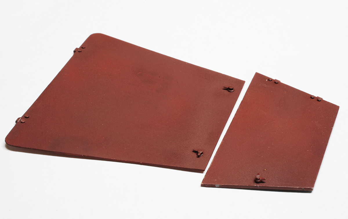
Bolt heads and locking mechanisms were added to the undersides of the covers.
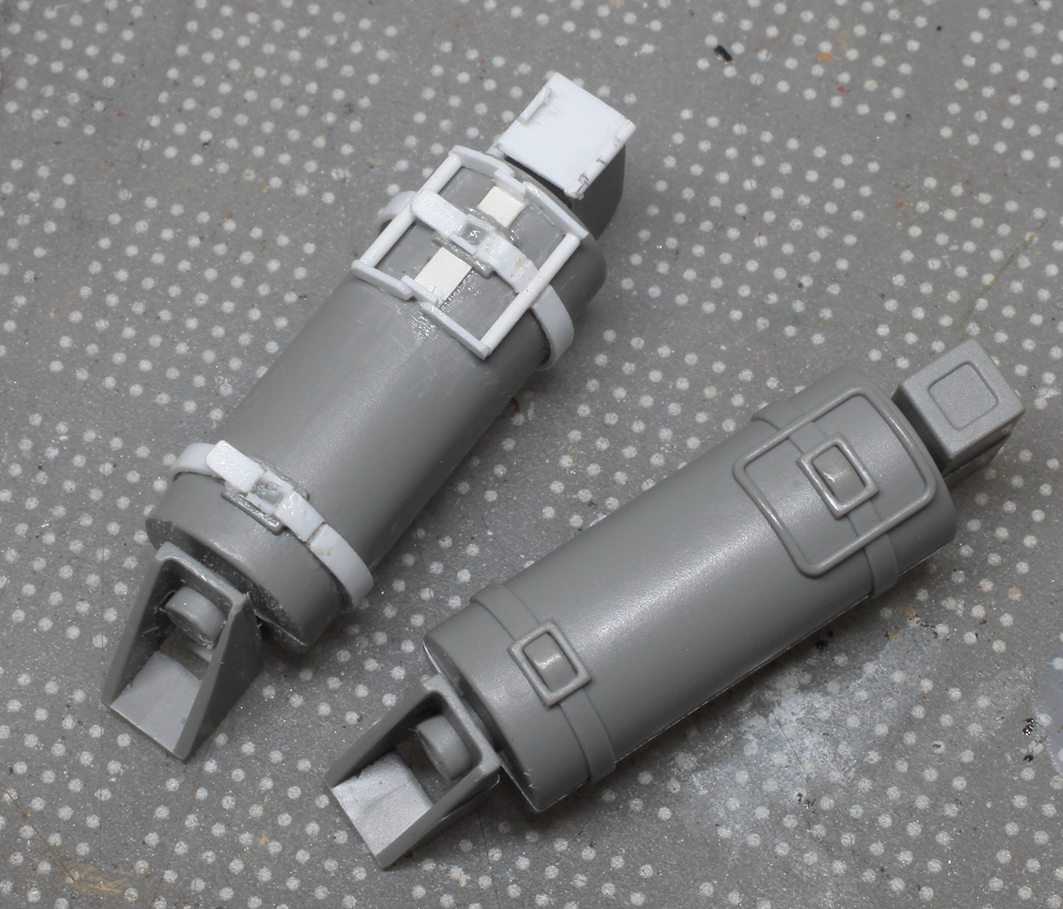
Only one of the two kit-supplied fire extinguishers was to be used so only one had extra detail added.
The extinguisher painted, decaled and glued in place.

Replacement MP 40 mounting straps and clips made using P/E bits and mag pouch is the modified kit part.

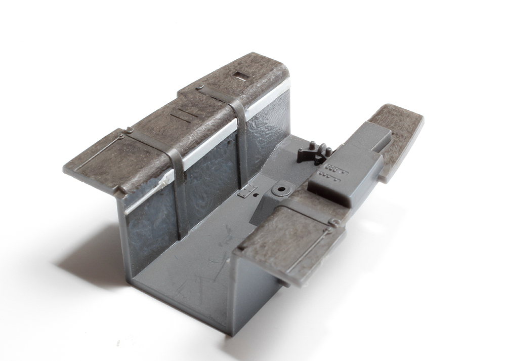
Scratch-built latch locks for large ammunition box door.

Scatch-built storage boxes.
Inexplicable notches in the lower rear corners of the kit’s upper side armour plates must be filled.
Headlight cover hinge detail was added using plastic strip and brass wire.

Scratch-built locking latch on the PaK 40’s tool box.

New springs for the rear doors were made by winding fine copper wire around an appropriate diameter brass rod and cut to the correct length.
Rear doors painted and weathered.
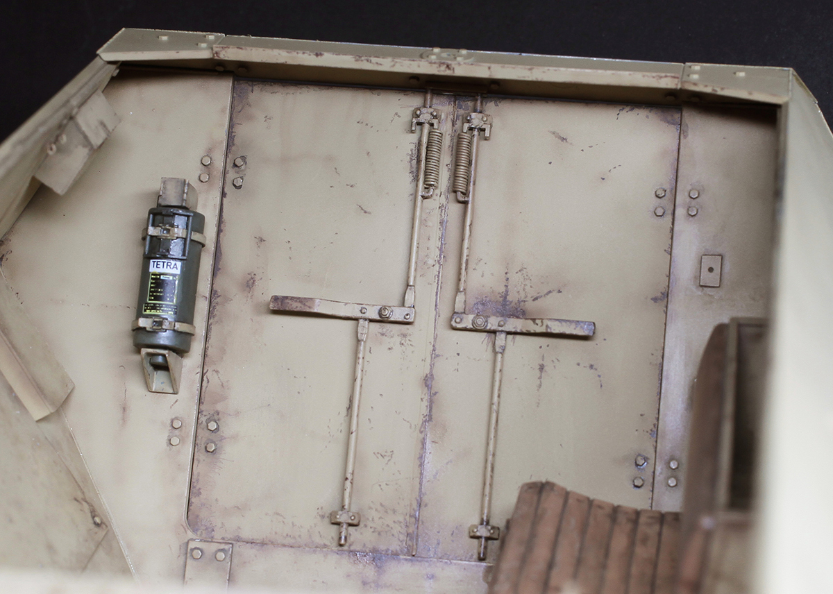
Springs, fire extinguisher and stowage boxes all in place.
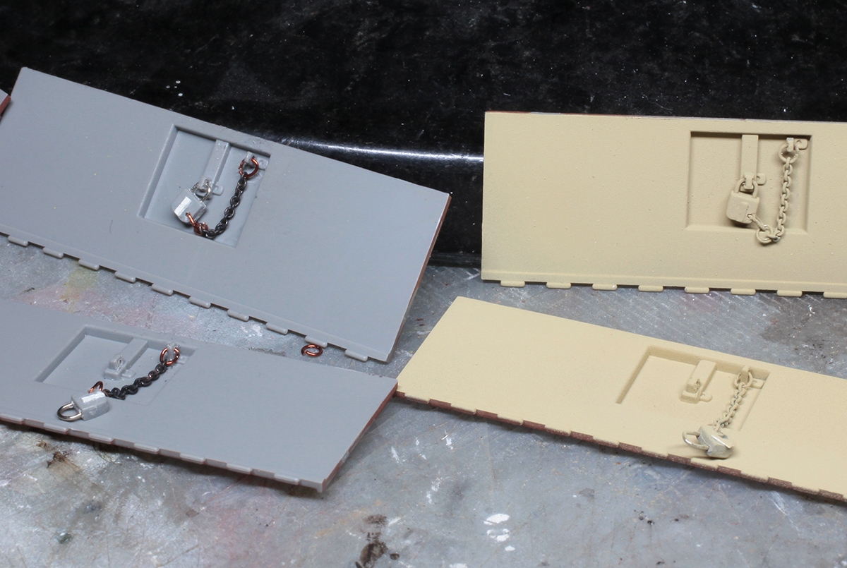
Outer hull side stowage bin doors with detailed padlocks and tiny, 45 links per inch chains. After I ordered the chain on eBay I started to worry that it was going to be too small but it turned out to be just right.
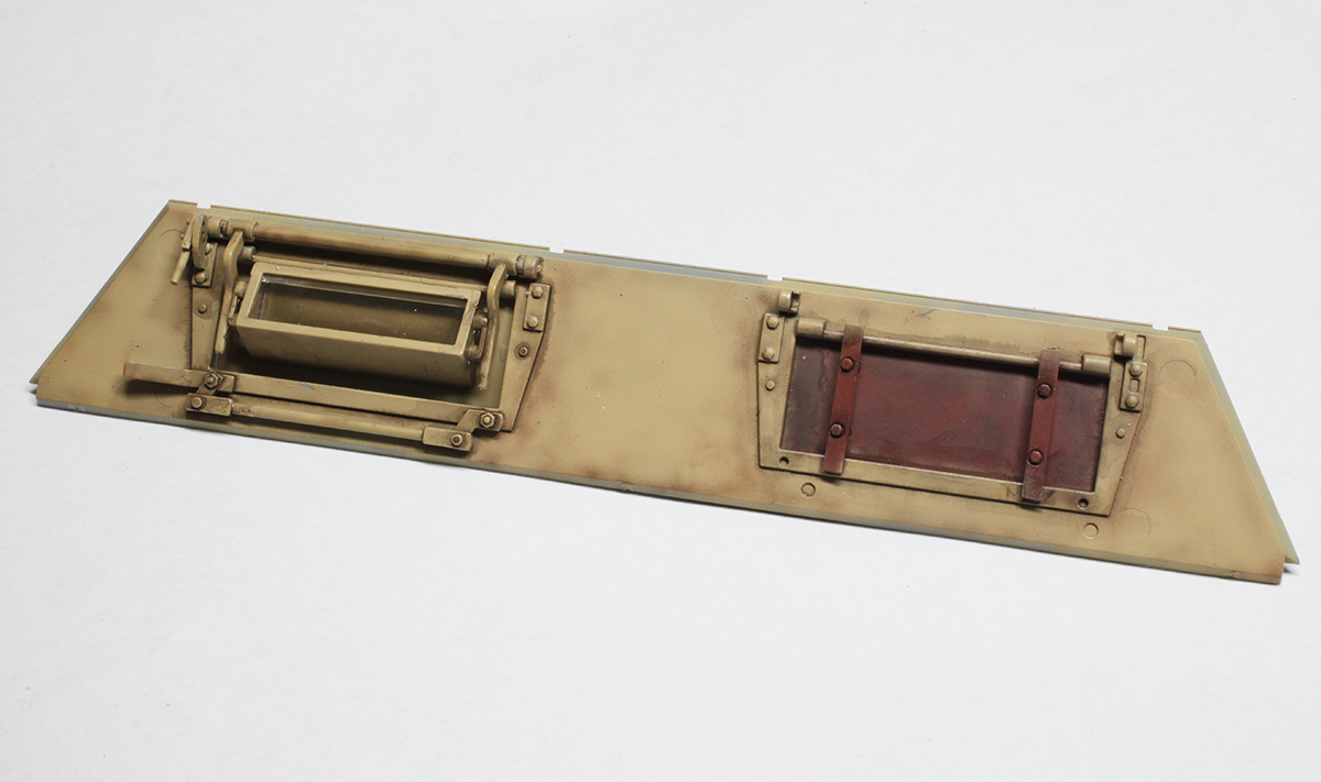
Driver’s vision port with armoured glass on the left and sealed-up commander’s port on the right.

Radio antenna mount with a new spigot made out of brass rod. As far as I can establish radios and their masts were rarely fitted to these vehicles.

MP 40 mounted in its new P/E clip and strap.

Interior of the driver’s and rear fighting compartments with rear bench seats, gun mount and 75mm ammunition stowage boxes fitted.

Basic construction of exterior complete. Camouflage application begins. Wheels were painted and weathered separately.

Working hinges allow engine hatches to be displayed opened or closed.
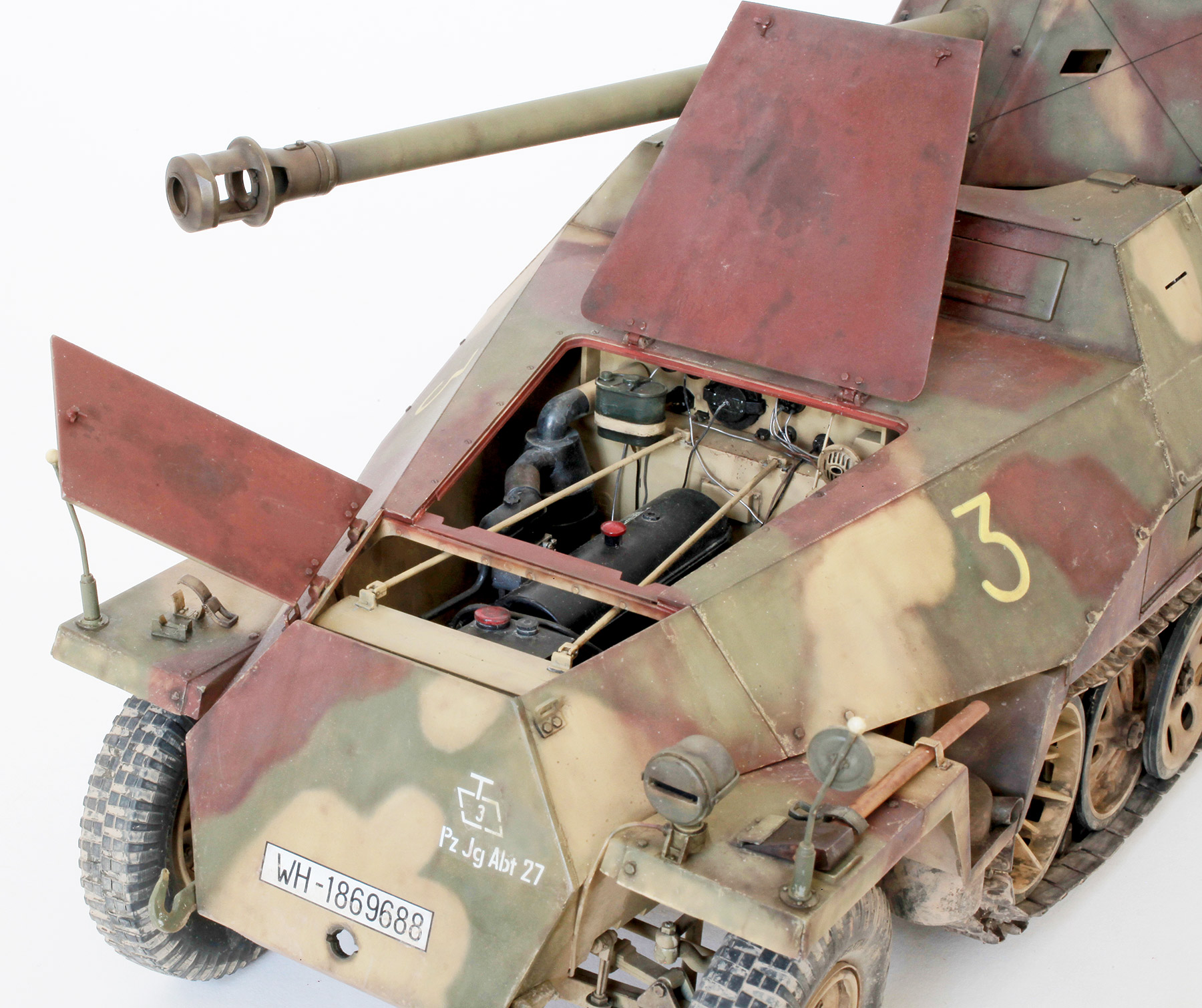
Open hatches.

Open side stowage bin. Some scratch built items were placed inside the bin plus a backing plate and latch were added to the locking box. This does not have a working hinge.
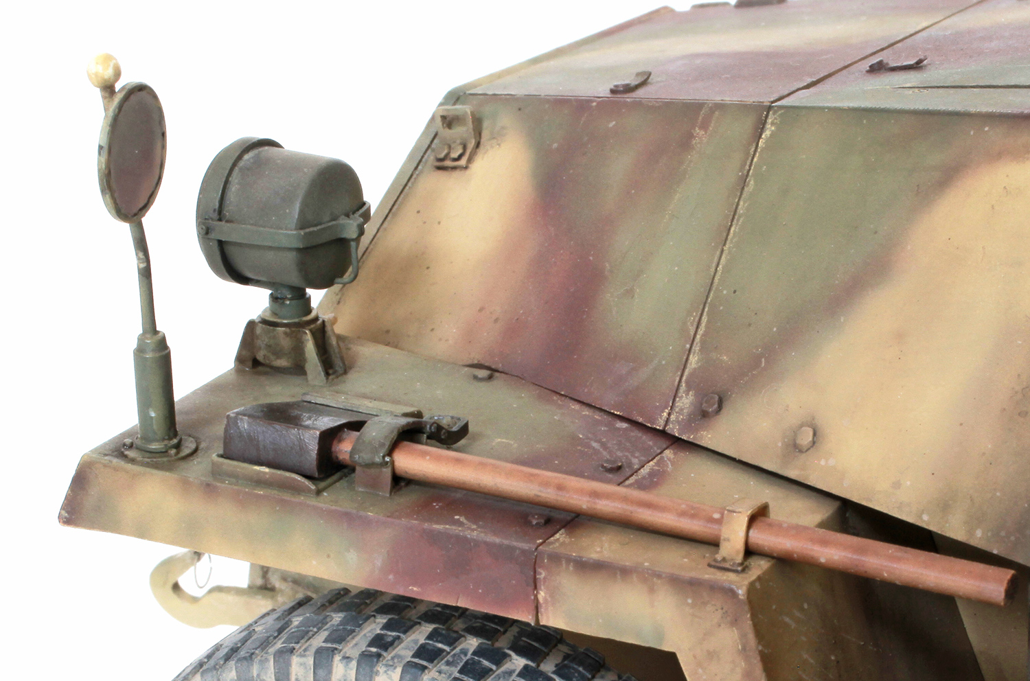
This close-up of the left mudguard shows some of the details added. These include scratch-built bracket and stowage latch for the axe; headlight cover hinge bracket; new, finer width feeler arm and ball, and if you look closely you can see a fine wire ring through the top of the front tow hook. The kit-supplied rectangular tie down brackets on either side of the radiator cover had their incorrectly positioned locating holes filled and the brackets were glued in the correct position about 2 or 3mm further forward.

Wider shot showing exhaust muffler. The end of the muffler’s pipe was drilled out to give it a thinner profile.

The PaK40 shell containers piled up on the gun aimers seat are 3D items from Blast Models. The gun cleaning rods on the lower right were scratch built by me.

Slightly different angle with a couple of helmets from Black Dog.

This shot shows other 3D items from Blast Models and Black Dog including Jerry can, helmets, 75mm shell cases and a couple of Panzerfausts.

BlastModels 3D printed bucket.

The same extras in slightly different positions. This shot also shows the chain added to the tow pintle’s locking pin.

Fighting compartment showing some PaK40 detail.
GALLERY


KōTARE 1/32 Me Bf 109K-4
KōTARE 1/32 Me Bf 109K-4

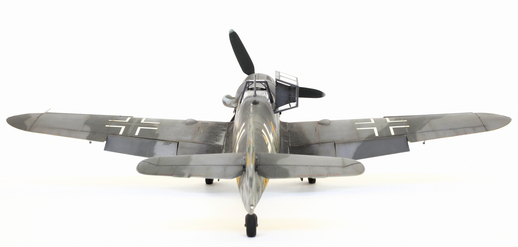
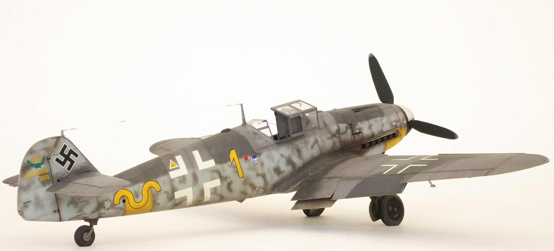
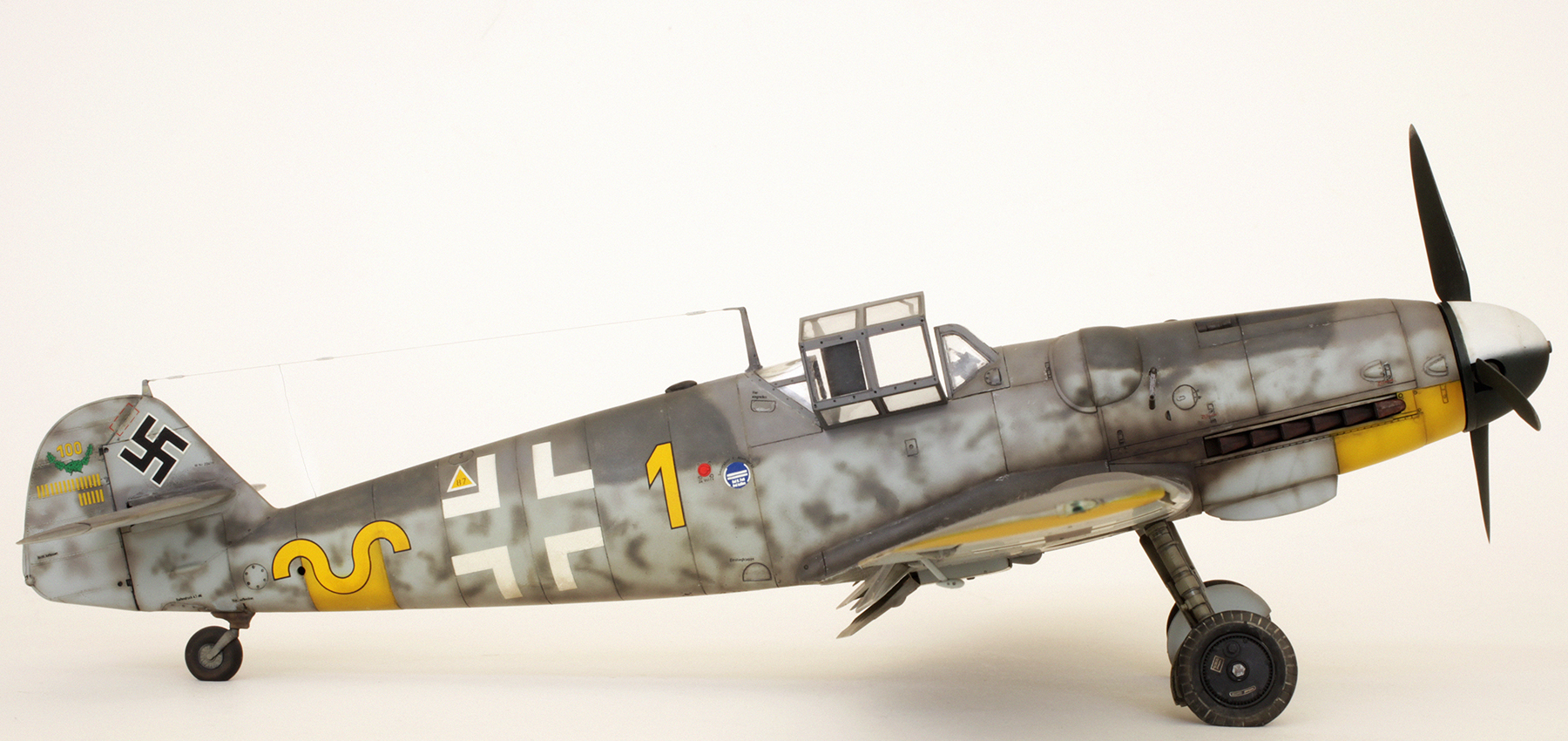
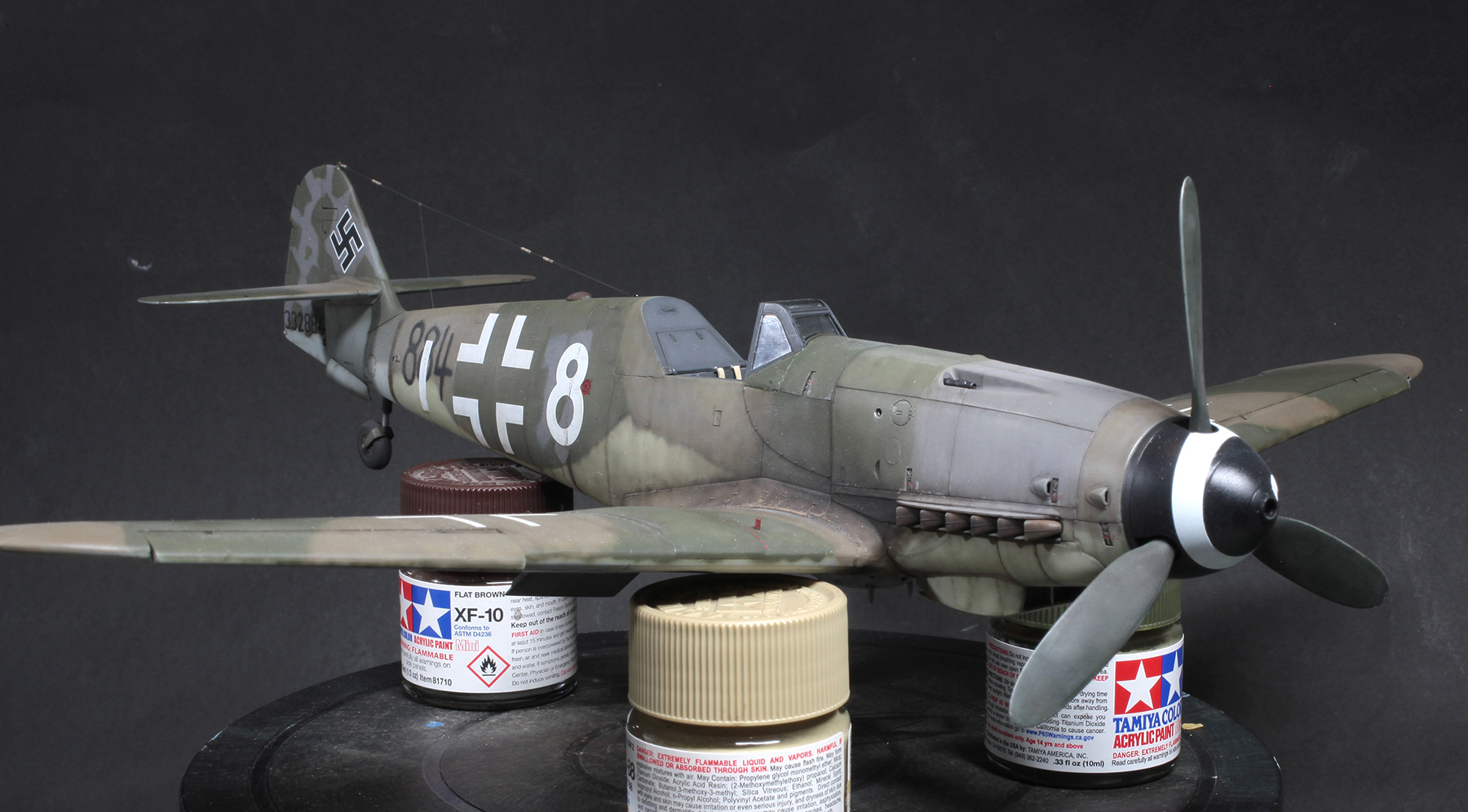
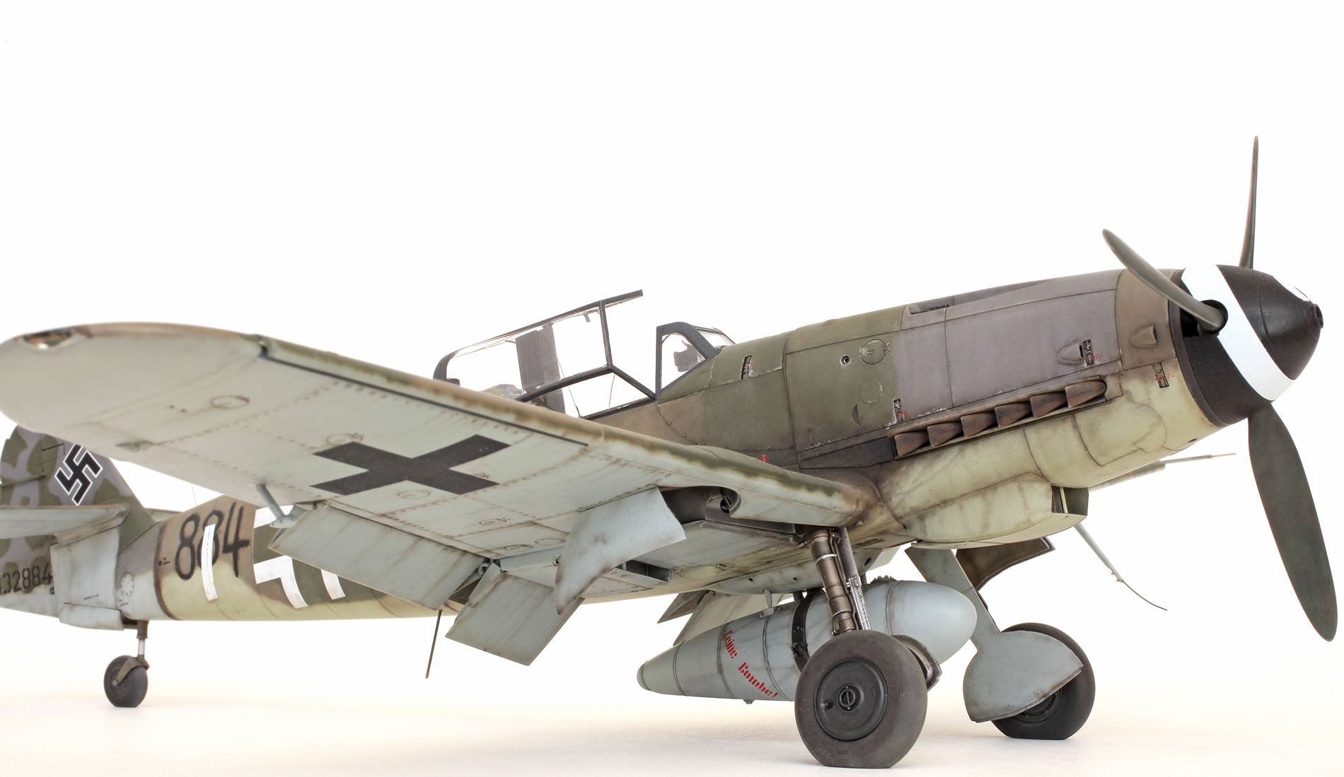
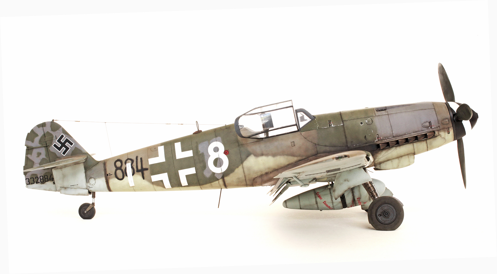
Aircraft W.Nr. 332884 of 9./JG 3. Abandoned at Leck or Pasewalk, Germany, April, 1945.

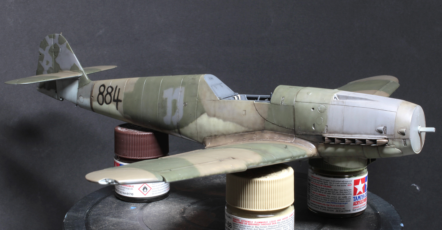
The model was delivered to me by Brett basically fully assembled. My job was to paint all the exterior surfaces (see above) and any other external parts. The main colours used were RLM76 Light Blue and RAF Sky on the undersurfaces and on the upper surfaces, RLM75 Grey Violet, two shades of RLM83 Dark Green and my own mix of a lighter version of RLM81 Brown Violet. I did add to or replace some of the finer parts, such as the D/F loop, the whip antenna at the end of the FuG 16ZY kit part, the fuselage mounted FuG 25a mast and the pitot tube.
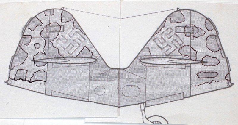
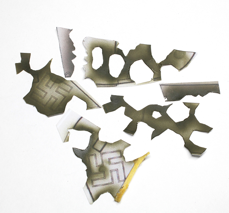
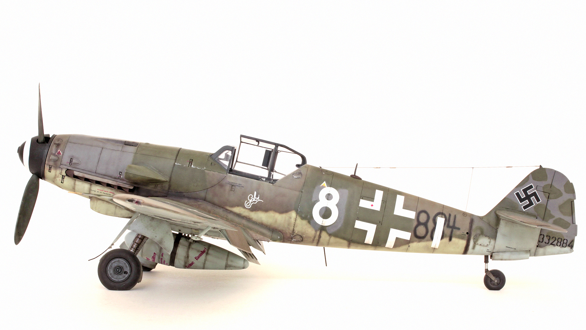
The hard-edged blotches on the upright tail surfaces were achieved by taking a copy of a line illustration from the old ‘MONOGRAM Close-Up No. 16 BF 109 K’ of a common pattern seen on many 109 Ks. Scaling this image to the correct size, I printed it onto self adhesive paper. Each blotch was given a hard outline and then carefully cut out with a sharp, new scalpel blade. The resulting stencils (see above) were stuck on to each side of the model’s tail which had already been painted RLM75 Grey Violet. RLM83 Dark Green was then sprayed over the cut out holes. The masks were removed and after a bit of cleaning up a pleasing result was achieved.

Shot of the under surface colours. Wheel wells were painted silver and weathered to represent unpainted aluminium. Weathering has also begun on the fuselage.
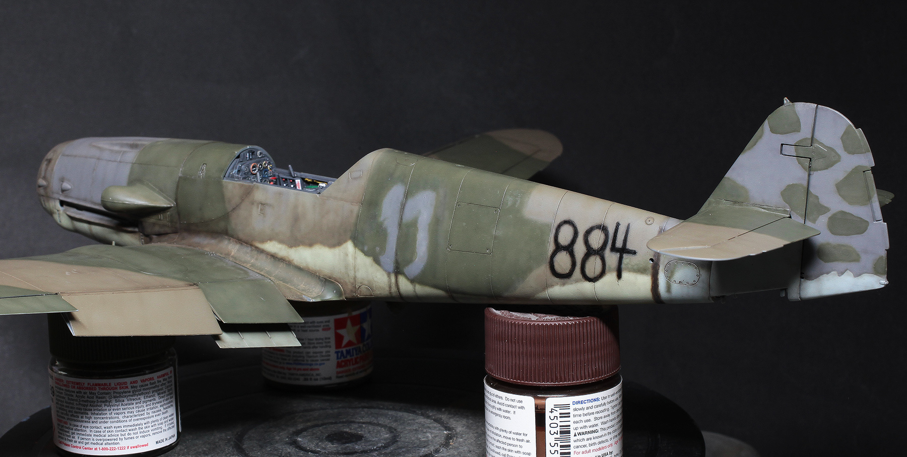
Painting and weathering basically complete. The AIMS decals that are supposed to represent the hand painted 884 numerals on the rear fuselage are very inaccurate so I hand painted my own.
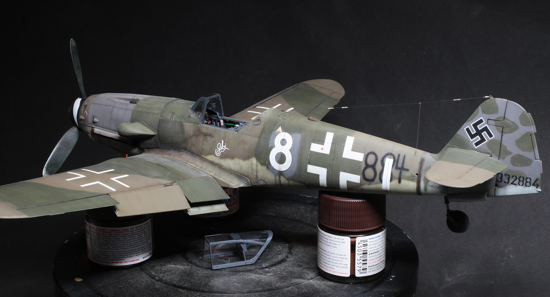
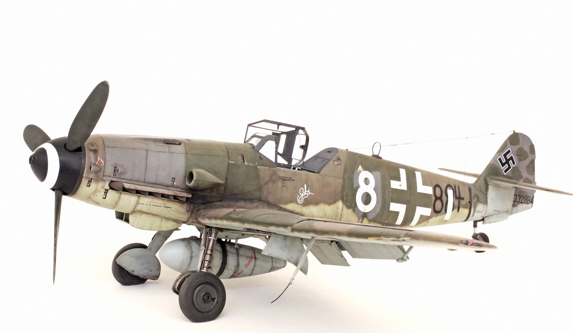
The model almost finished, just waiting for all the dangly bits to be put in place. Note also in these pics that the radio antenna wire has been attached. This is made from nylon invisible thread with 3.5mm lengths of .3mm brass tube as insulators.

The dangly bits.
GALLERY


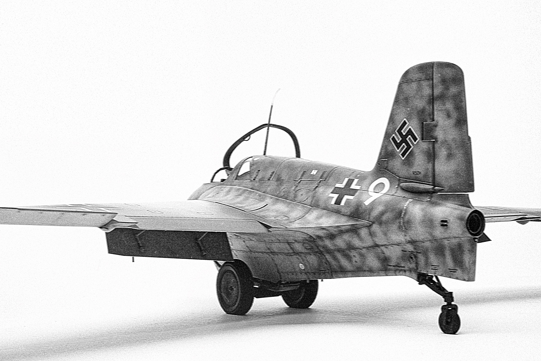
MENG 1/32 Me163 ‘KOMET’
MENG 1/32 Me163 ‘KOMET’

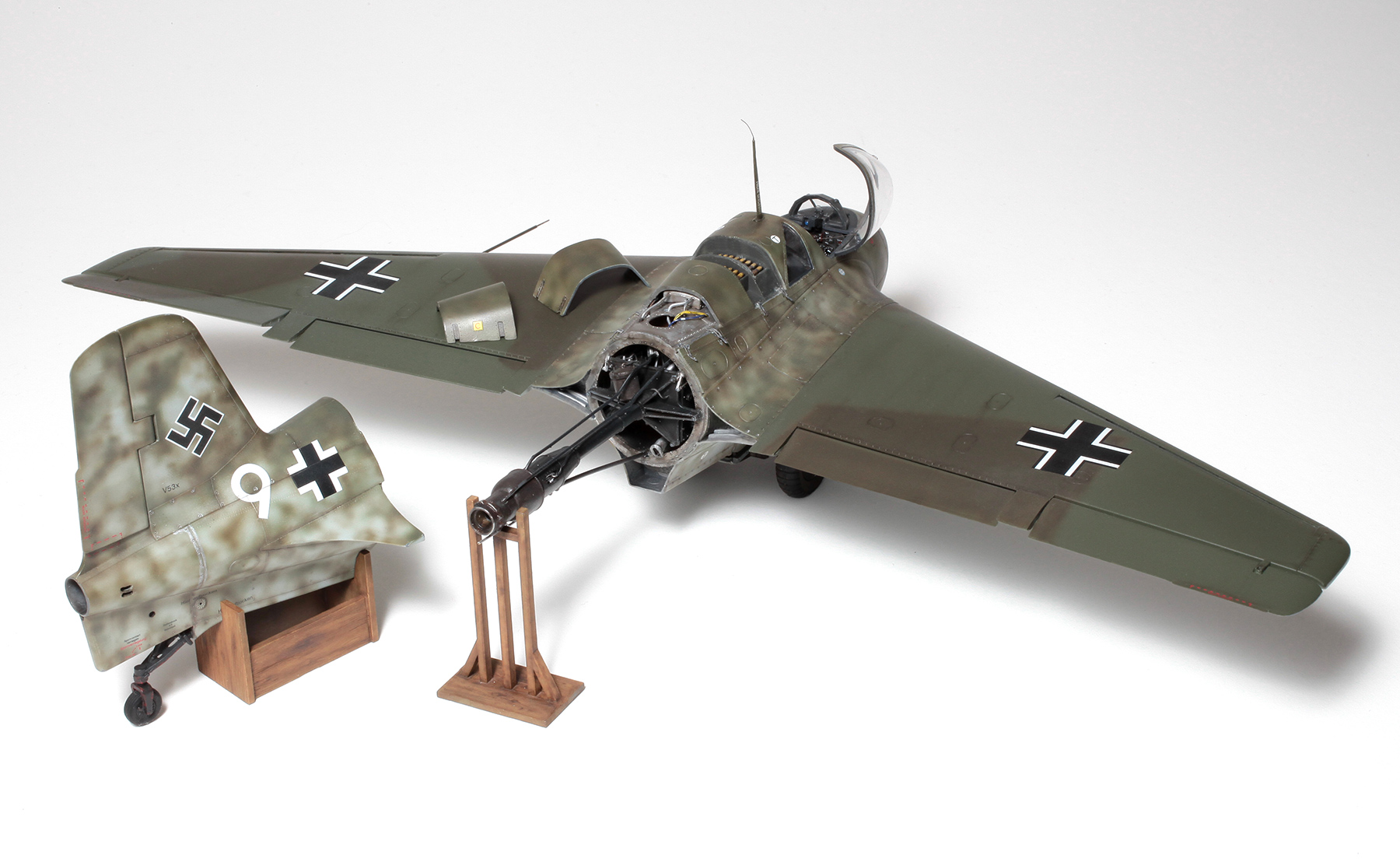
Messerschmitt Me163 point defence rocket fighter of JG400.

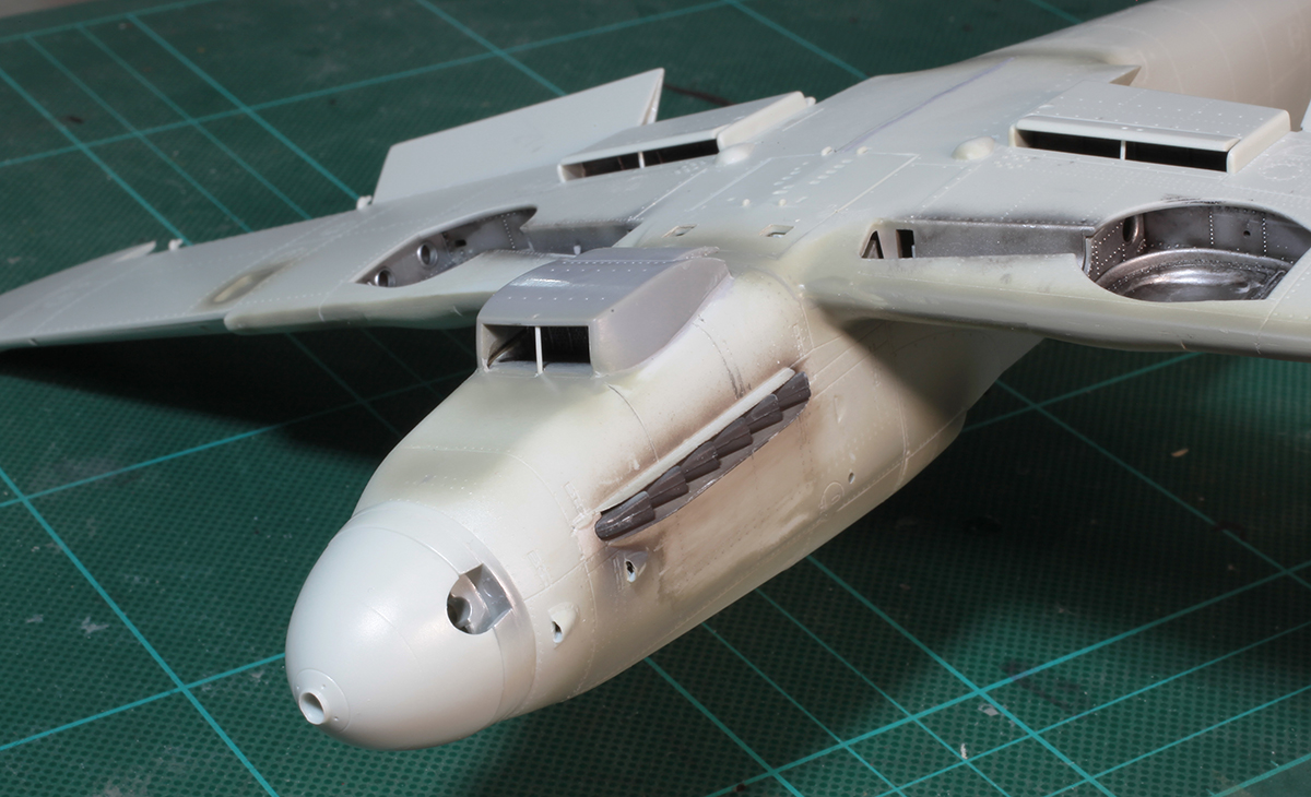
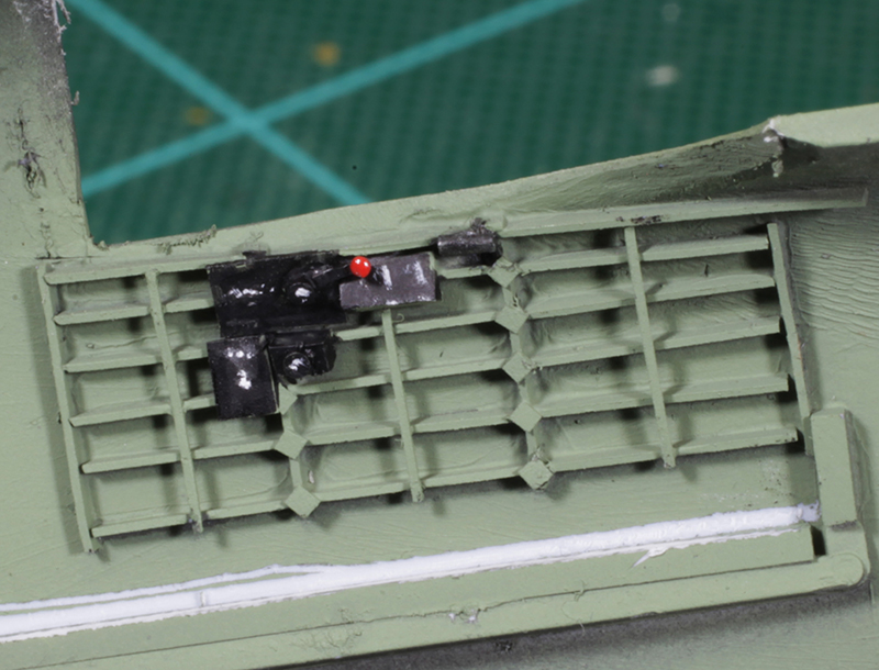
Kit HWK 109-509 A-2 liquid-fuel rocket motor with some extra plumbing added using mainly fine lead wire.
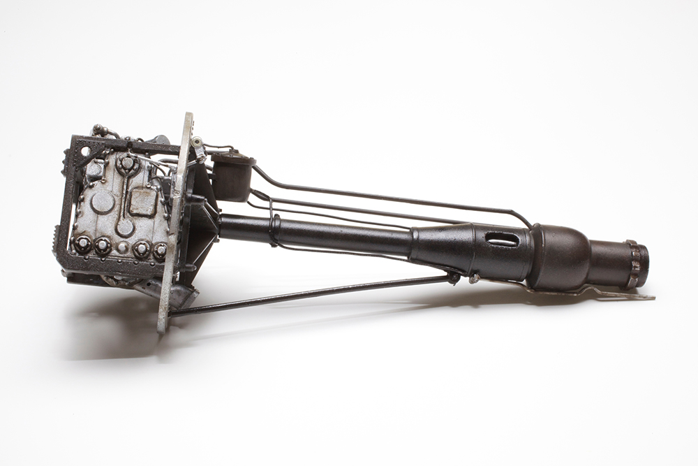
Giving up to 1700 kg of thrust, this motor could propel the Komet to well over 900 km/hr.

Rear end of the turbine. Once fitted to the fuel tank and inserted into the main fuselage this fine detail will never be seen again.

Fire walls for either end of the 1040 litre fuselage T-Stoff fuel tank. When looking at photos of museum examples I could see that they were painted this dark orange colour which I think was a fire proof lacquer paint called Flieglack 7142 or 7130.

T-Stoff fuel tank with fire walls and rocket motor attached and ready for installation.
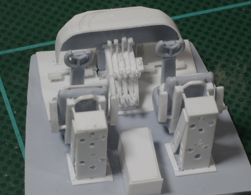
Cockpit tub with extra strapping and surface detail added to the 60 litre T-Stoff cockpit side tanks.

Complete cockpit tub (sans instrument panel) with a bit of extra detail added.

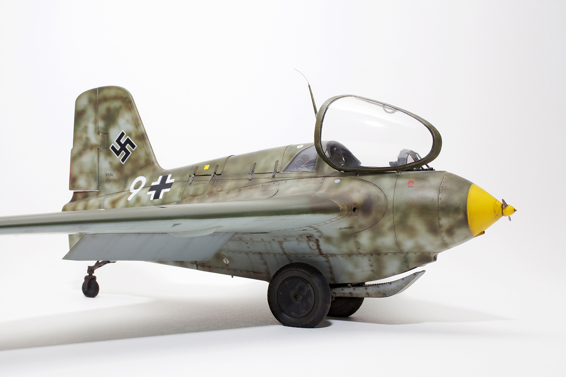
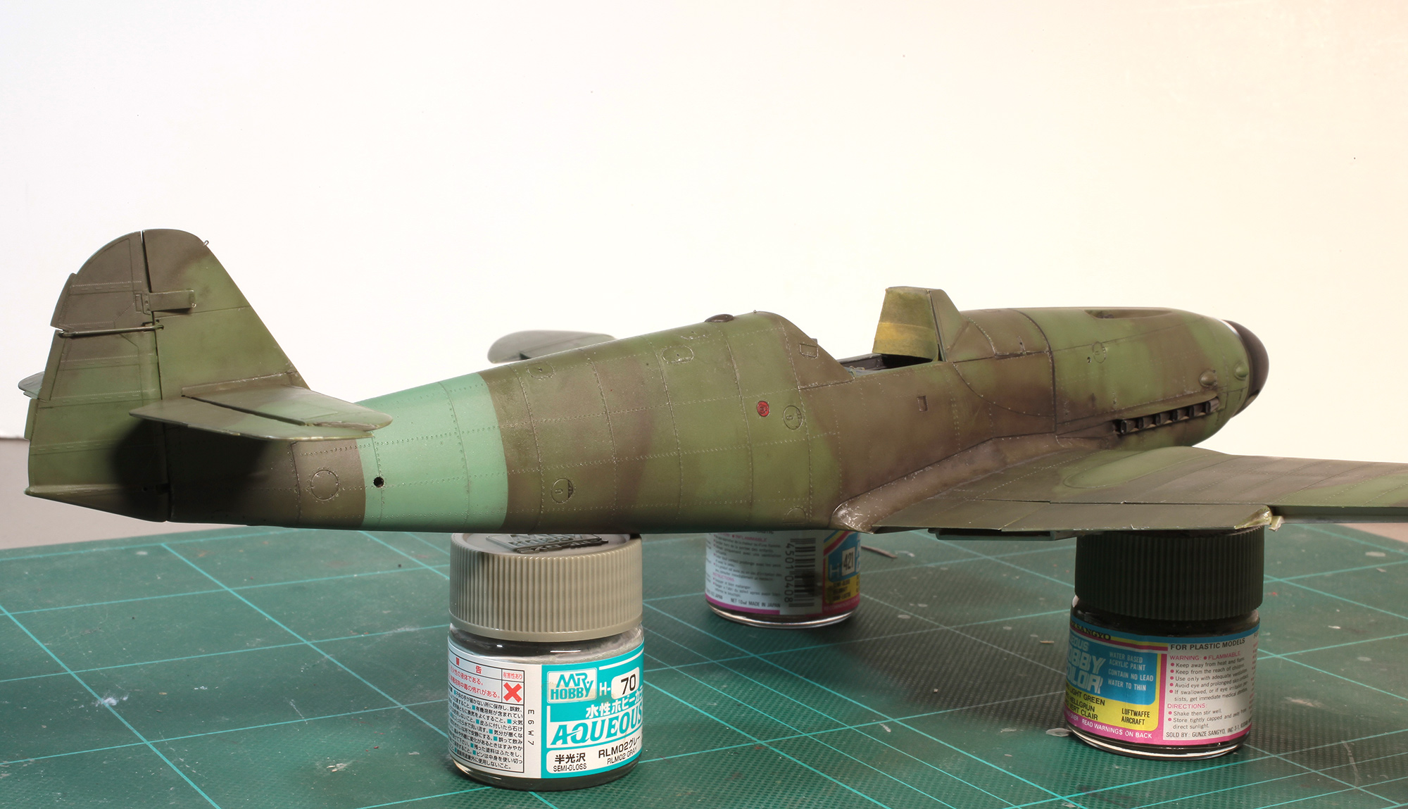
Main assembly complete. Nose cone has been sprayed yellow and masked. Glue joins have been filled and given a quick squirt of RLM 02 to make sure no more filling is needed.

RLM 76, 81, 83 cammo complete awaiting decals and weathering.

Decals have been applied and fine weathering has been carefully sprayed over panel lines and rivet heads using my very thin black/brown mix. Some subtle, general streaking was also done using the same mix.
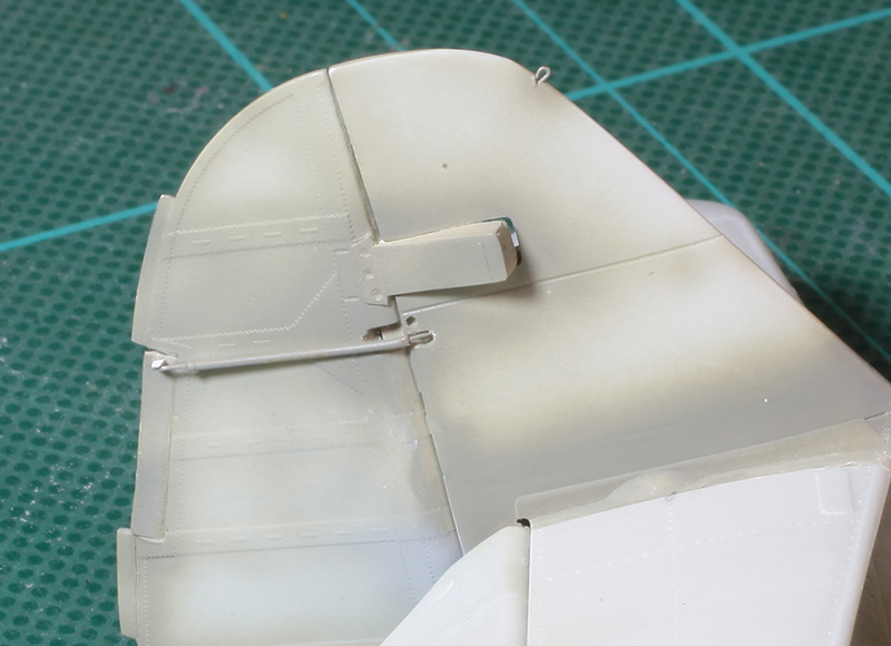
The painted and weathered landing skid. I have repositioned the skid’s mounting brackets so it sits (as per reference pics) at about halfway from its fully extended position.

The main reason it has taken me so long to post these pics is that I was very unhappy with the heavy tread on the kit-supplied soft vinyl tyres. No aftermarket replacements were available at the time and as this was a commission build, the model has long since been out of my possession. I recently rediscovered the original pics and decided to use my Photoshop retouching skills to smooth the surface of the tyres to a much more realistic look. Hope this cheat is OK with you guys.
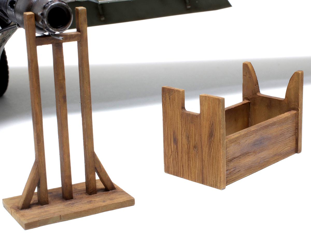
Some panel line and grain detail was scribed into the wooden holding brackets using a scalpel.
GALLERY


Dragon 1/48 Ju88G-1 Nachtjäger
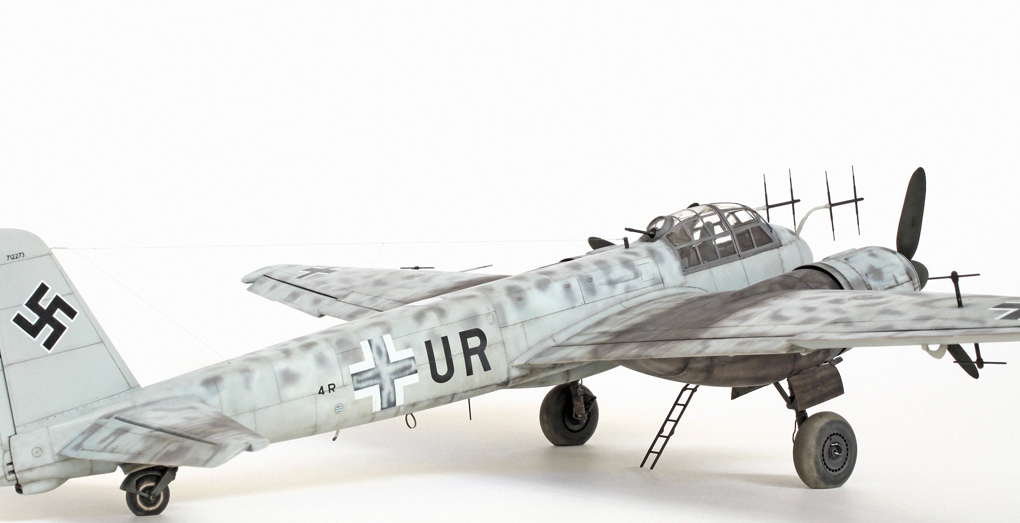
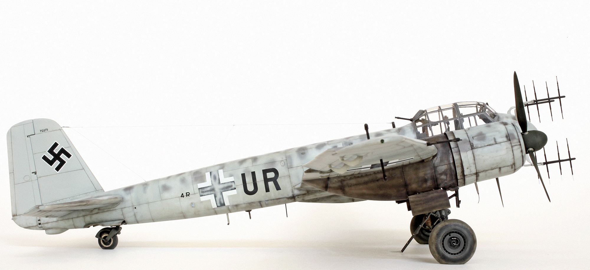
Junkers Ju88G-1 ‘NACHTJÄGER’ of 7. Staffel/NJG 2

Before the G-series all night fighter versions of the Ju88 were based on a modified A-series fuselage. The new G-series had a re-designed fuselage to better fit the demands of a night fighter. These changes included the removal of the lower defensive gondola from below the nose for less drag and also to lower weight. The Ju88A vertical tail unit was replaced with the larger and squarer Ju188 fin and rudder for better lateral stability. The G-1 was also fitted with the standard, more powerful armament consisting of four forward-firing 20mm cannon housed in a streamlined underbelly gun pack. Some G-1s had combinations of forward or upward firing cannon fitted to the nose but these caused a blinding muzzle flash for the pilot and so were not adopted. Some later G-1s were fitted with a pair of upward firing ‘Schräge Musik’ cannon behind the cockpit but not this early one.
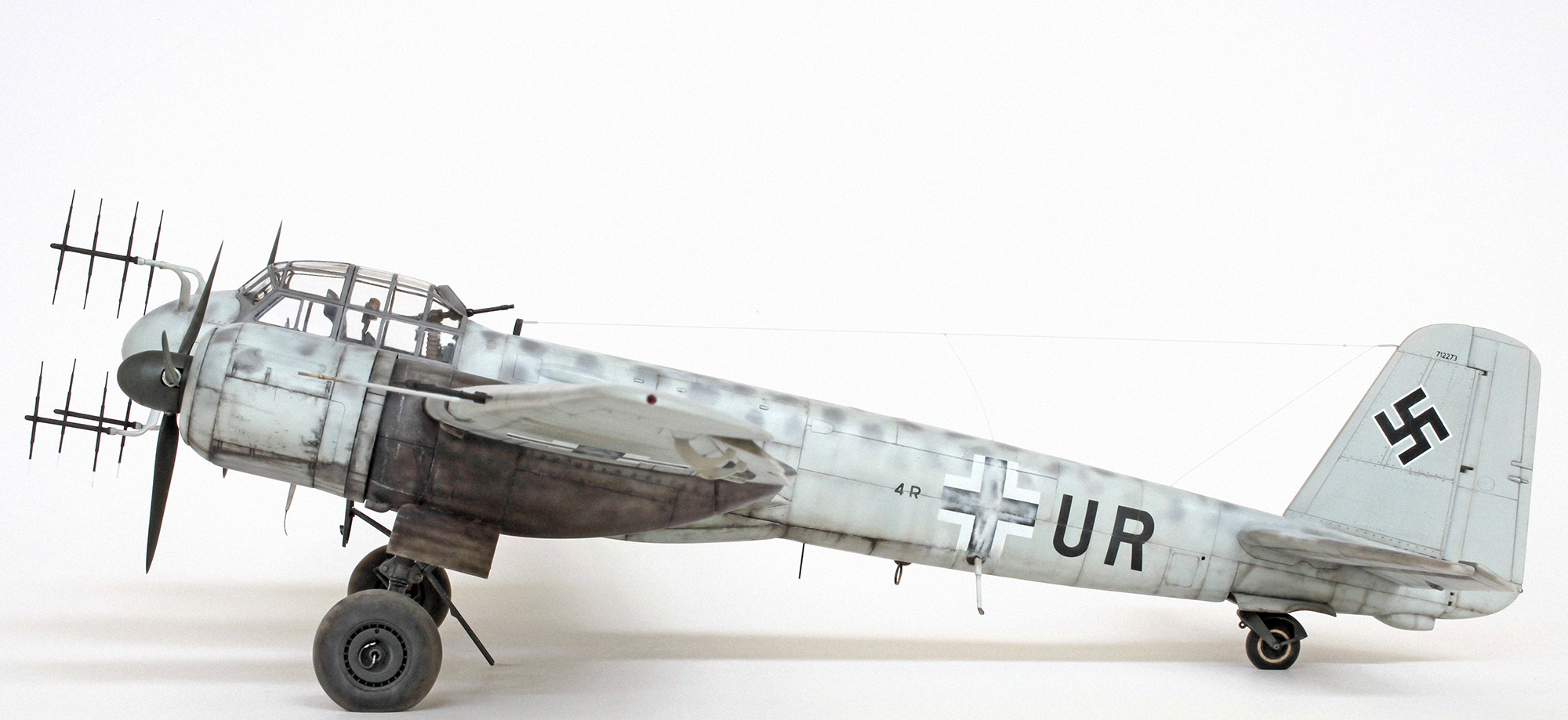
The subject of this model is an early production G-1 (W.Nr. 712273) from 7./NJG 2 piloted by Obergefreiter Hans Mäckle. At 04.25 hours on the 13th July 1944 Mäckle, after getting completely lost and flying a reciprocal course, landed on the emergency landing strip at Woodbridge, Suffolk thinking he was near Berlin. The capture of one of Germany’s latest night fighters, being intact and fully equipped with the latest radar and radio, meant that this valuable prize was extensively tested and photographed which makes it a great subject for the modeller.
CONSTRUCTION AND DETAILING

Cockpit interior with a bit of extra detail consisting of scratch built safety harnesses made from lead foil and fine copper wire, hydraulic lines added to the rudder pedals made from fine solder wire and a new scratch-built headrest was added to the radio operator’s seat.
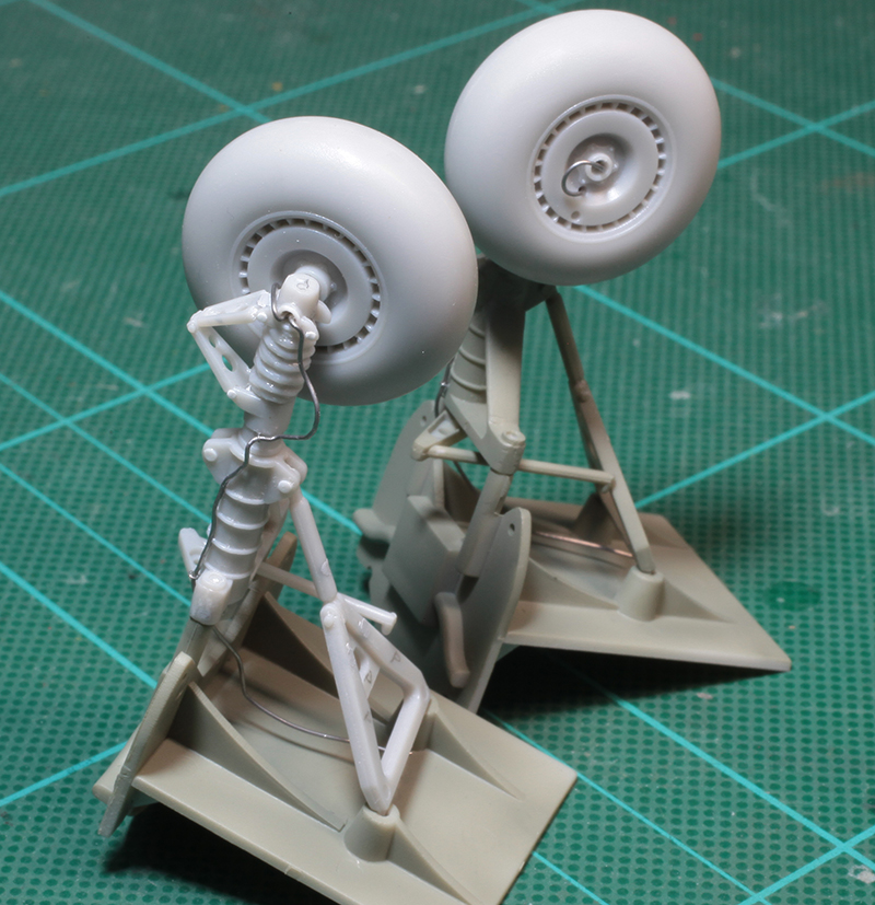
Main undercarriage with fine solder brake and hydraulic lines added and a bit of hinge detail added to the oleo scissors and retraction arm attachment. All tyres, including the tail wheel, were given flat spots before being painted and fixed in place.

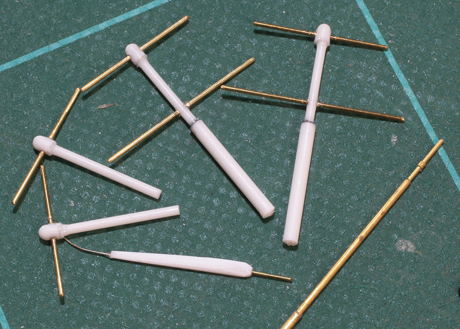
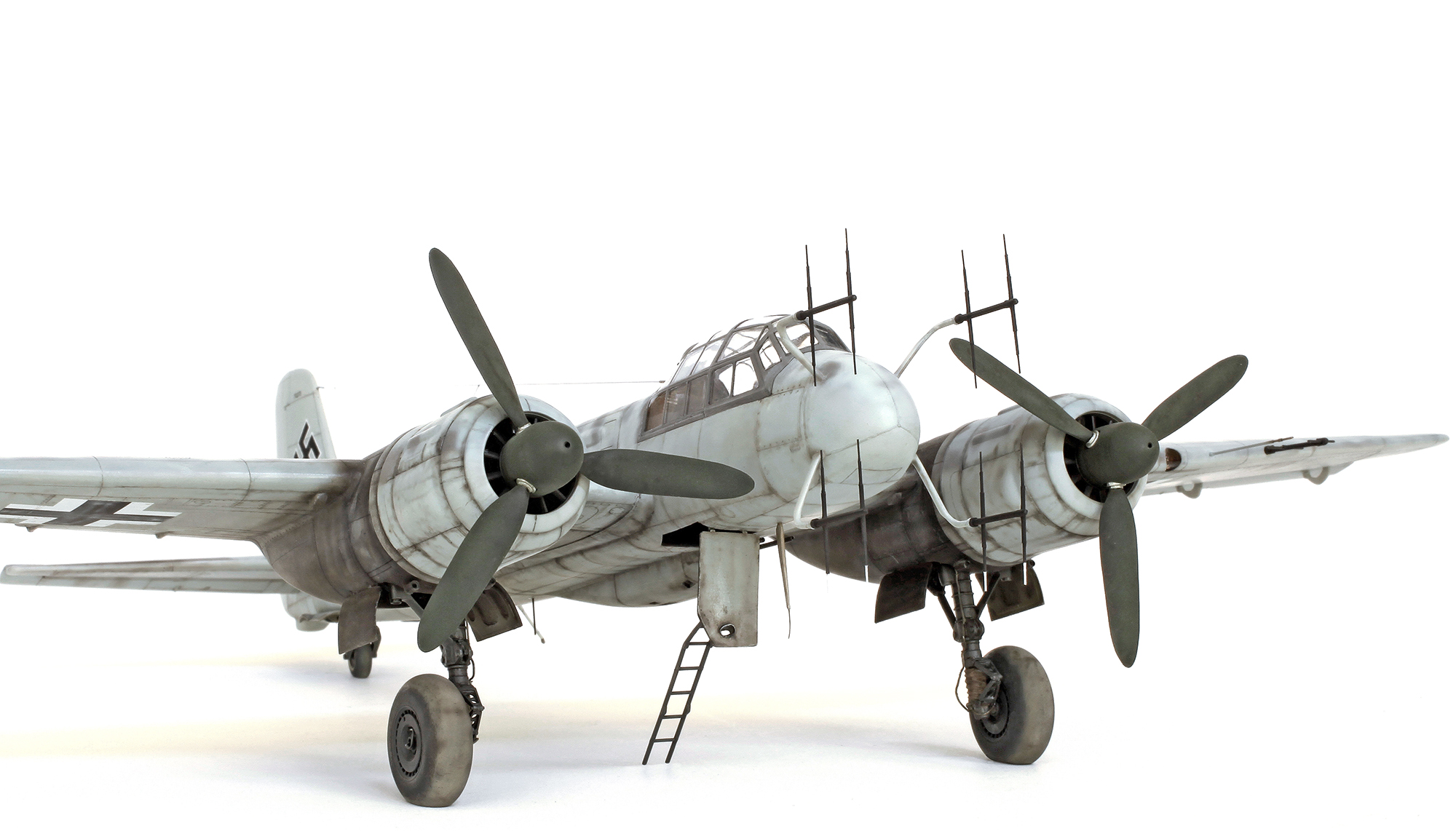
Next big job was to replace the kit Lichtenstein SN-2 radar dipoles with much finer and cleaner examples made using Albion Alloys SFT2 telescoping brass tube and wire and .040″ plastic rod from Evergreen. For a bit of added strength the end of each dipole was drilled and a short length of brass wire was glued in place. A corresponding hole was drilled in the mounting points on each of the main radar arms and, using CA glue, each mast was firmly fixed in place.
The kit’s wing mounted FuG 227 Flensburg antennae masts, pitot tube and FuG 16 antenna were all replaced with scratch-built items made using brass wire, tube and plastic rod.
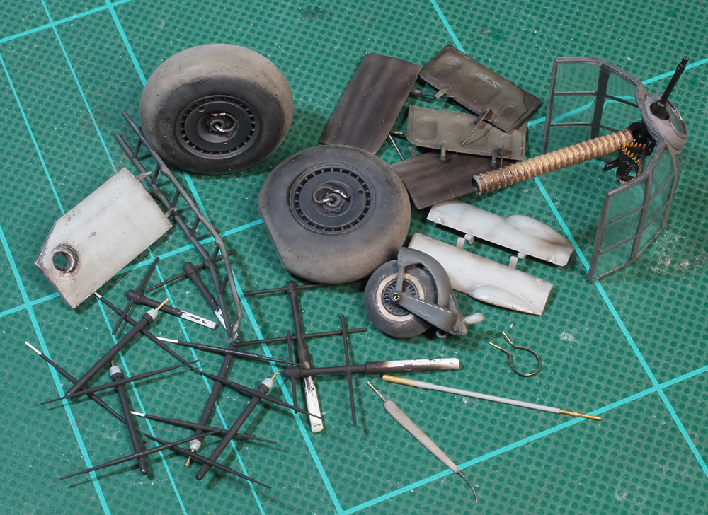
All the dangley bits painted, weathered and waiting to be attached. The crew access door on the left was later replaced with a better detailed scratch-built one.
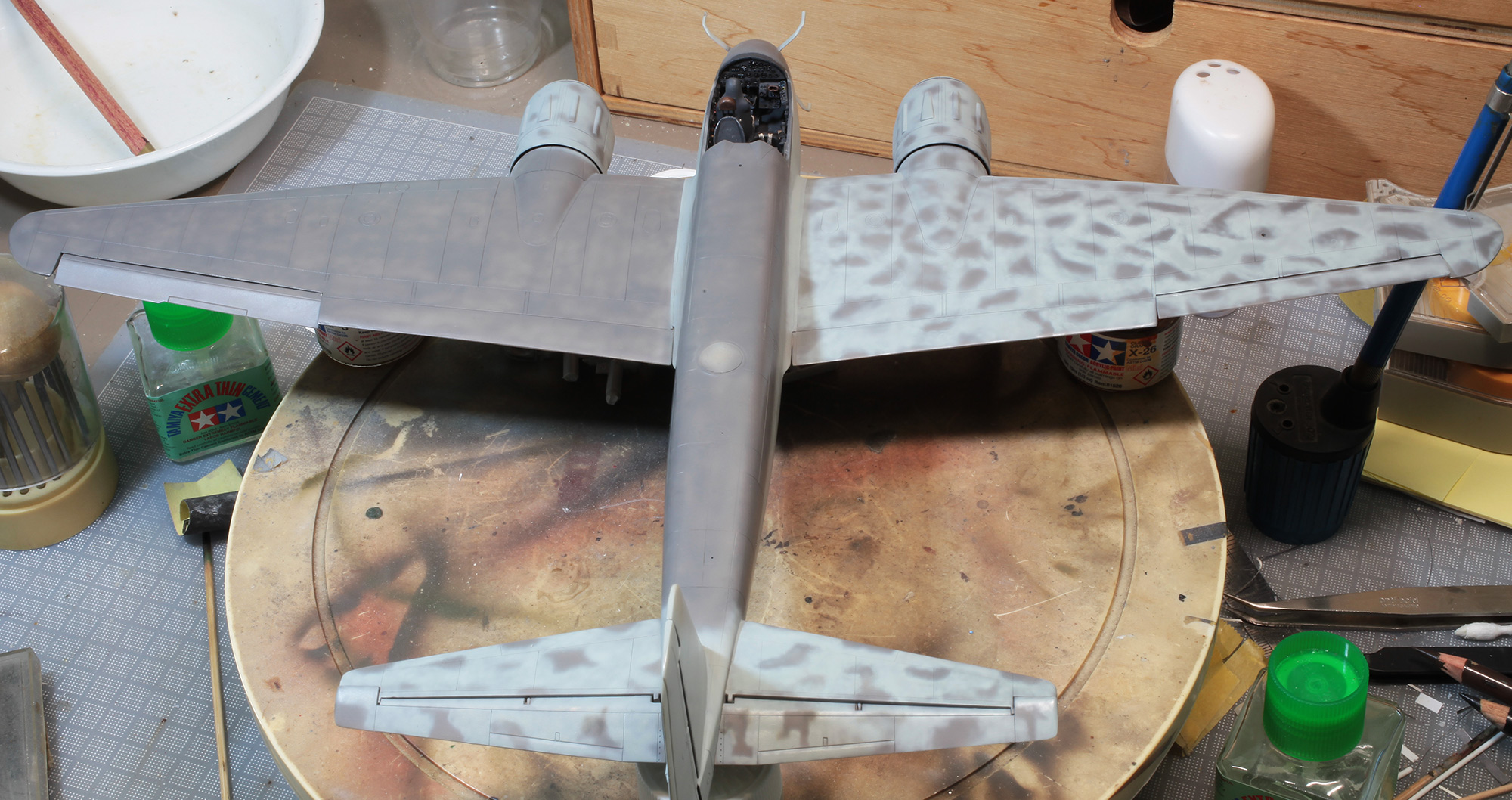
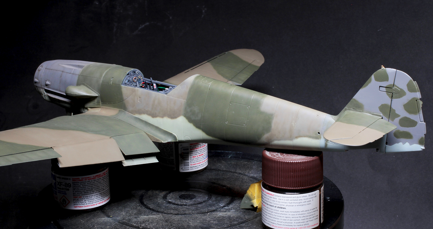
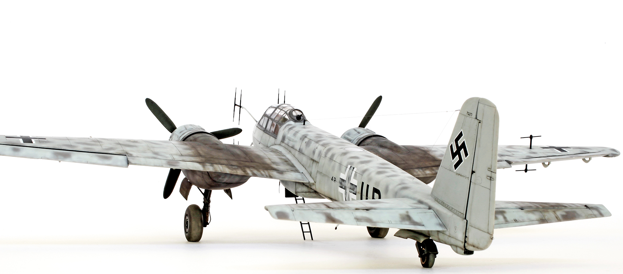
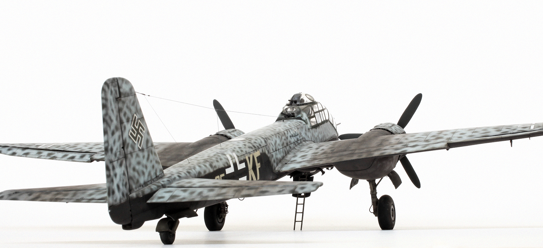
This is my interpretation of factory-applied German night fighter camouflage—RLM76 Light Blue under surfaces and vertical tail, with solid RLM75 Grey-Violet on all horizontal upper surfaces. The upper surfaces were then given various cross hatch, squiggle and lattice patterns of RLM76 Blue. In some factories and sometimes in the field other colours were added to this upper scheme using various patterns and colours. Even though the description of this type of scheme is usually described as being a mottle of Grey-Violet applied over the top of an overall Light Blue base I think my interpretation is right. Note also that my application of the upper colours is fairly patchy.
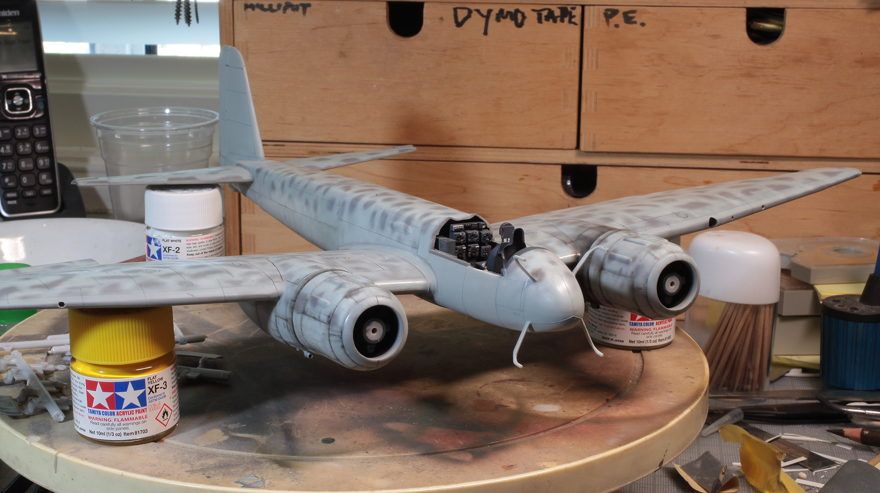
Upper surface cammo now complete and weathering has begun.

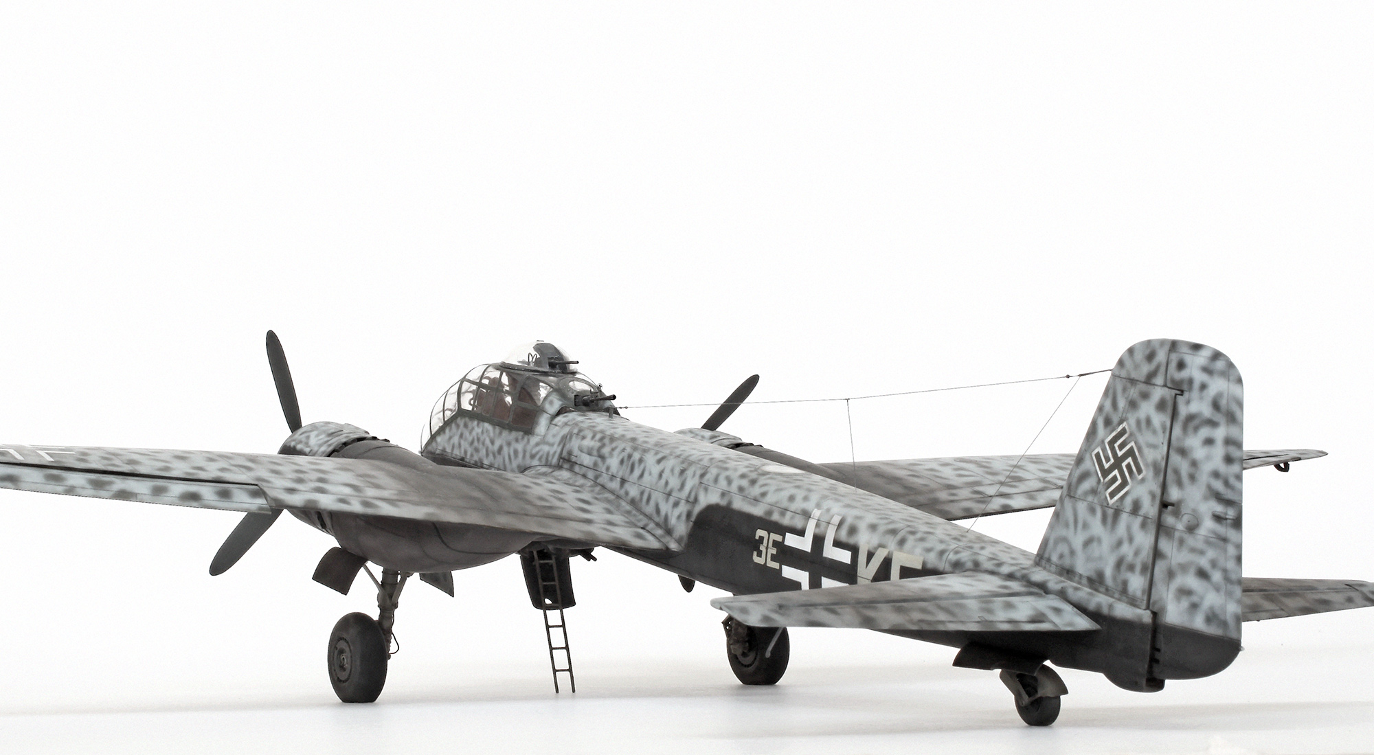
The undersurfaces were fairly heavily weathered as per a very clear photo of the inner wings and central fuselage of this aircraft. This was applied using a fine paint brush but mainly with my old Aztek airbrush.
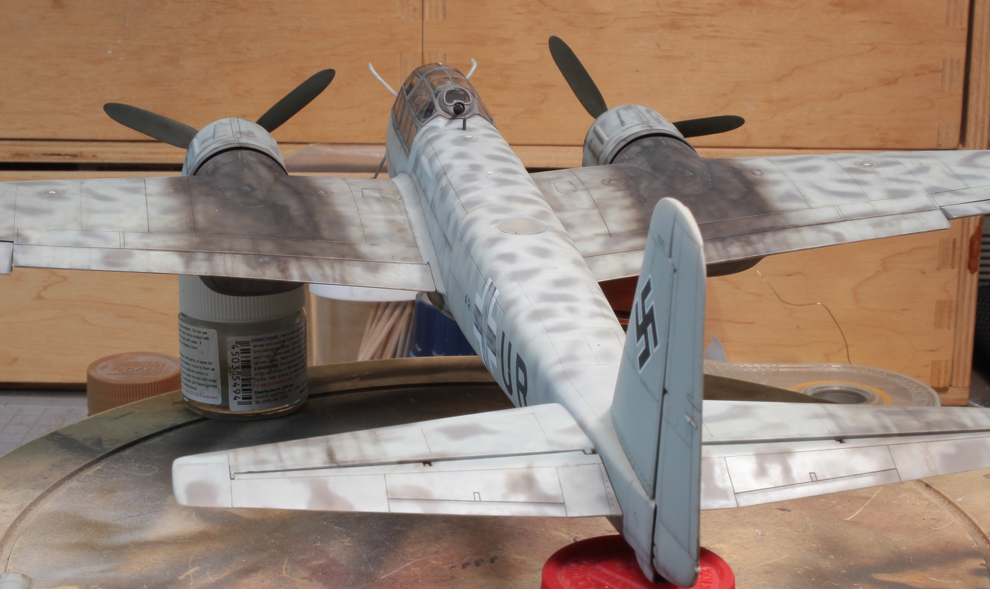
Decals and heavy exhaust staining added to upper and lower surfaces.
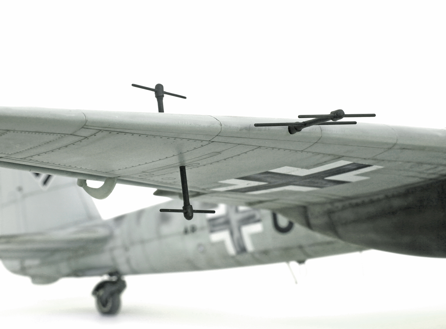
FuG 227 Flensburg radar detector antennae on the starboard wing. These masts picked up the RAF bombers Monica I.F.F. transmissions and greatly aided the German pilots in locating and homing in on their targets. The port wing was only fitted with the leading edge mast.

Close-up of port engine weathering. Also notice the dark yellow/orange lens on the landing light and the rough overspray of RLM76 over the black centres of the underwing and fuselage balkenkreuz.
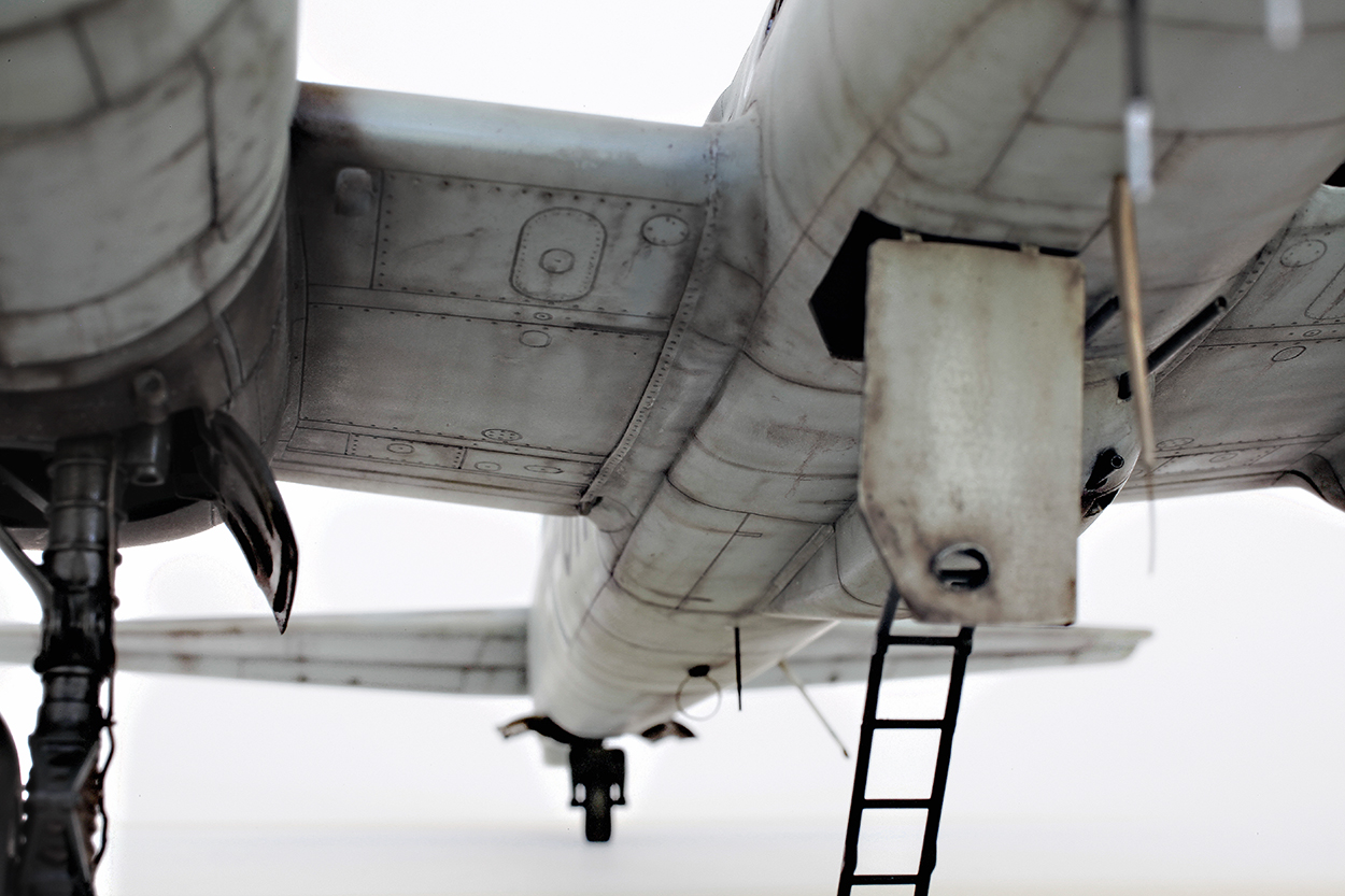
Dirty belly.

Starboard engine cowl and oily exhaust staining of this dirty bird.
GALLERY


Dragon 1/48 Junkers Ju188E-1 ‘Rächer’
Ju188E-1 ‘Rächer’
I built this one back in 1994 and it was finished in the markings of an aircraft from KG6, Erprobungstaffel.

If I remember correctly most of the lower surfaces were painted first. They were sprayed with a coat of flat black that had a few drops of red brown added. Panel lines were highlighted by carefully spraying them with pure flat black. The upper surfaces of the model were then given a hard edge splinter cammo scheme of RLM70/71 greens. Over the top of this a very carefully sprayed lattice pattern of RLM76 light blue was applied. This pattern varied, being heavier on horizontal surfaces of the wings and tail. A much finer pattern was applied to the fuselage, engine cowls and vertical tail. The lower surface black mix was then carried on up the sides of the fuselage and engine cowls overlapping the 76 lattice at the desired demarkation lines.

The BMW radial engines used on Ju88 and 188 aircraft always seemed to run very dirty. The heavy exhaust stains on the upper and lower wing and tail surfaces were added using a very thin mix of about 20% flat black and 80% red brown. These were built up gradually and were heavier along panel lines and around any hatches. Any chips or scratches were applied with a Prismacolor silver pencil.
GALLERY


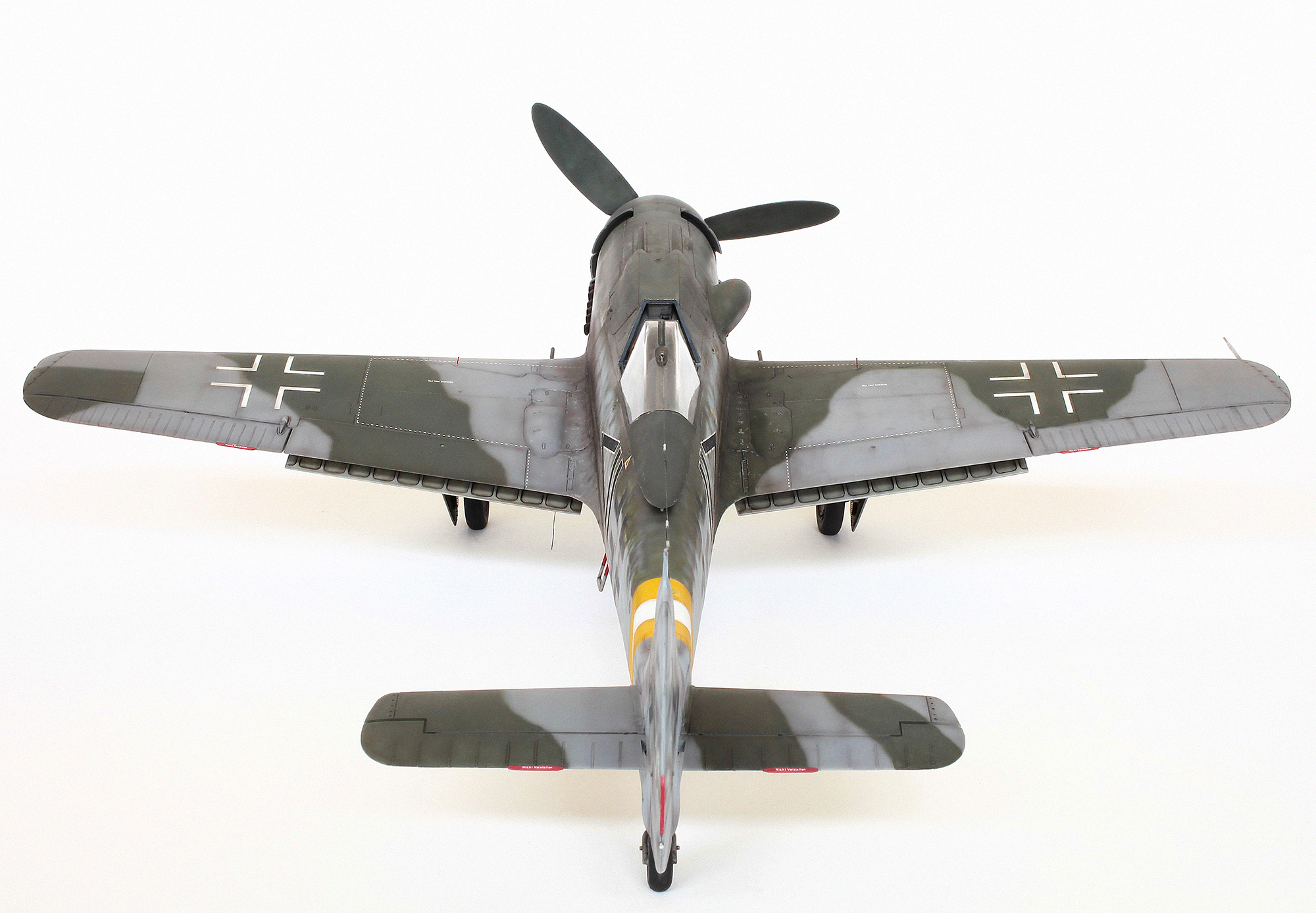
Hasegawa 1/32 FW 190 D-9
Focke-Wulf Fw 190D-9 of JG 2, flown by Fw. Werner Hohenburg of 4/JG 2.

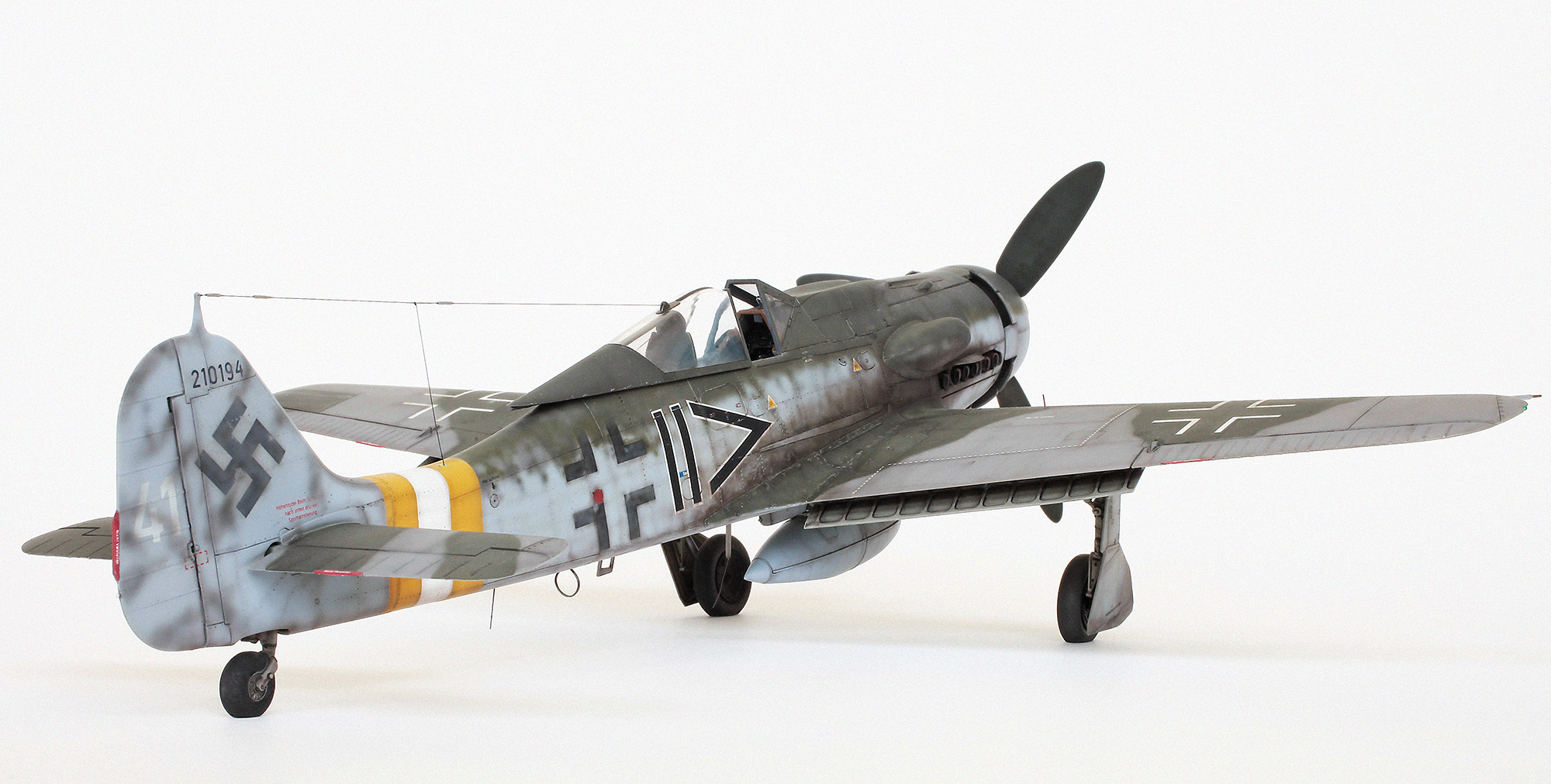
Hohenburg was shot down in this D-9 by antiaircraft artillery after attacking St Trond airfield during Operation Bodenplatte on January 1st 1945.

Hohenburg, who carried out two hundred combat sorties and achieved thirty three victories, survived being shot down and spent the remainder of the war as a POW.

I built this model back in 2003 and, as it has always been a favourite of mine, thought it was time for a bit of a tidy-up and to take some new pics.

The prop blades were dirtied up with a patchy dusting of very thin Tamiya XF- 57 Buff and then spots and streaks of RLM70 Black Green.

In the original build the fuselage crosses and the tail swastika (as per reference photos) were given a very light overspray of RLM76. I now thought this looked a bit too light so they were darkened up by giving them a careful spray of my black/brown mix, being very careful to just soften the edges a little.

The pics were given a bit of extra grain using Photoshop.

THE END
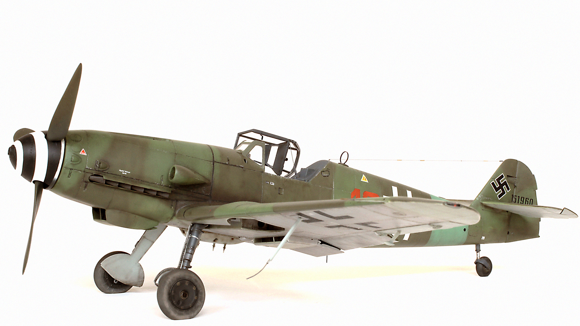
REVELL 1/32 Me Bf109 G-10 Erla
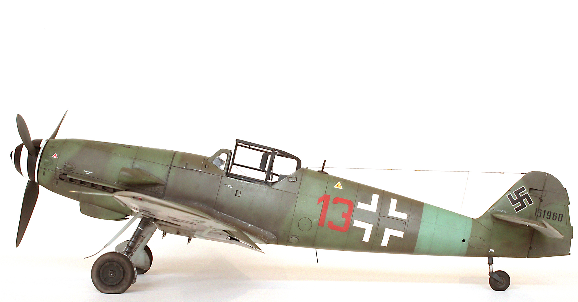
Erla built Messerschmitt Bf 109 G-10 of 2/JG27

Red 13 of 2./JG27, Schwerin-Görries/ Germany, mid April 1945. Claes Sundin (whose beautiful illustration of this aircraft was my main inspiration for this build) states “that this Bf 109 G-10 was found intact, belly-landed in a field. The W.Nr. on its rudder is a qualified guess as it is known that the Gruppen flew this type of G-10 from the 151XXX block and some of them were camouflaged in this overall scheme of RLM 81/82. This machine had been quoted as being Black 13 however, by this time, 2./JG 27 was only using red tactical numbers.” Claes may be wrong about the red 13 but I think it looks great on this scheme.
Build shots

Cockpit with a fair bit of extra detail added. The very ordinary kit rudder pedals were replaced with the much better items from the Hasegawa G-10 kit.

Kit joystick with some extra detail added.
Cockpit painted and weathered with the beautiful HGW micro fibre fabric seatbelts added to the seat.

Interior installed. Decals for the instrument dials were sourced from an old Hasegawa 109 decal sheet. Each dial face was cut out and applied separately.
Revi gunsight from the Hasegawa 109G-10 kit (with a bit of extra detail added) was used in place of the underwhelming kit offering.
The kit’s chin radiator is way too shallow so I replaced it with the corresponding deeper part from the Hasegawa 109 kit.

The kit’s very narrow exhaust stacks were replaced with the broader Hasegawa offering. This required a bit of surgery to make them fit which included thinning of the exhaust shrouds, which I was going to do anyway. Also the end of each stack was carefully hollowed out.
A new push rod for the rudder’s trim tab made from brass wire and tube replaced the kit part. The fine wire loop near the top of the tail fin makes for a very secure attachment point for the radio antenna wire. A corresponding loop was added to the fuselage just behind the cockpit opening for attaching the other end of the wire.

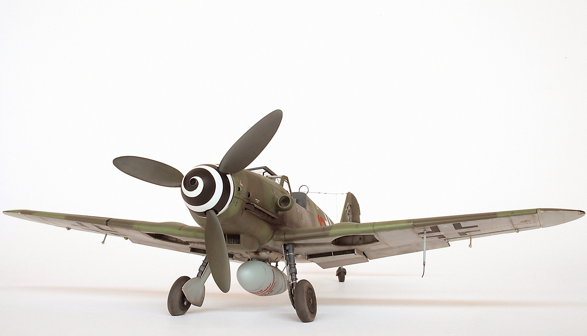
The small scoops on either side of the nose were very carefully hollowed out using my motor tool and a sharp scalpel blade. Note also rivets added to spinner.
This shot shows the initial application of the cammo colours and the JG27 green Reich Defence band. Weathering is also well underway and you can also see that the entire model has been riveted.

Decals have now been applied but as I couldn’t find any appropriate decals for the fuselage Balkenkreuz and red 13, I cut masks and sprayed them on. The speculative W.Nr. on the tail was made by cutting individual numbers from the kit decal sheet. The insulators on the antenna wire were made by cutting 2.5mm lengths of 0.5mm x 0.3mm brass tube and threading onto the nylon mono filament. Once in position each one was secured with a tiny drop of CA glue.

Patchy bare metal lower wings with wingtips, ailerons and horizontal tail surfaces in RLM76. All weathered with my black/brown mix.

Open canopy securing strap and spring were made from very fine copper and brass wire. Securing loops for the radio antenna wire and safety harness buckles were also made from fine wire. DF loop was made from a narrow strip of flat P/E brass from the spares box.
GALLERY


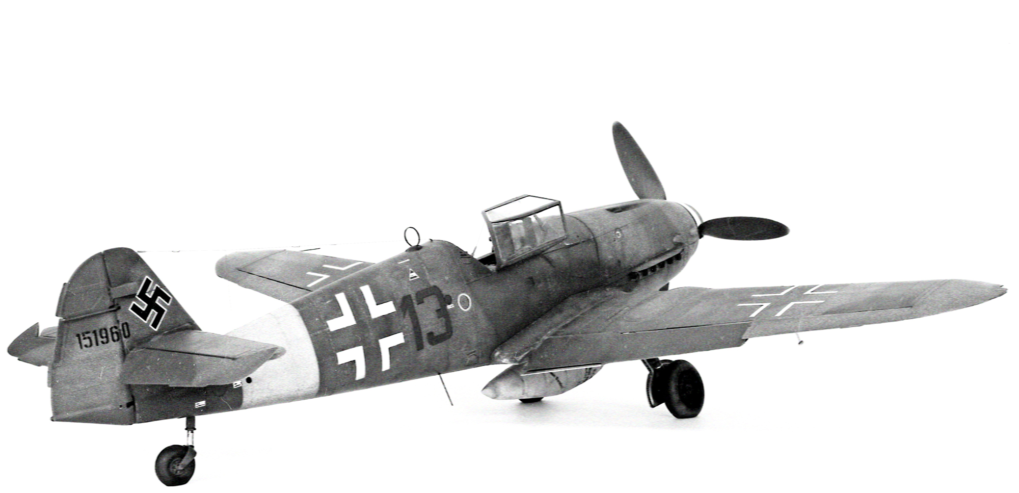
Given the black and white treatment to try and match my B/W reference photo shows how it could easily be interpreted as black or red “13”.
Paints used:
Gunze Sangyo Aqueous Hobby Color- H-65 RLM70 Black Green, H-70 RLM02 Grey, H-417 RLM76 Light Blue, H-421 RLM81 Brown Violet, H-422 RLM82 Light Green.
Tamiya Acrylic- XF-1 Flat Black, XF-2 Flat White, X-18 Semi Gloss Black, XF-24 Dark Grey, XF-64 Red Brown.
Tamiya Lacquer- LP-70 Gloss Aluminum.
Winsor & Newton Galleria- Matt Varnish
1/32 Special Hobby Fieseler Fi 103 (FZG 76) / V-1
V-1 BUZZ BOMB
At sites in northern France, on the night of 12 June 1944, the first Vergeltungswaffen (V-1s) were pushed onto their launching rails. At midnight they were launched and, with their pulse jet engines crackling, set course for London.
Construction

First thing I did before the fuselage/engine halves were glued together was to drill out the access hole on the vertical tail fin and remove the moulded-on support bracket detail from the engine’s blast tube. New internal and external bracket detail was added using various Evergreen plastic strip and rod. In hindsight I wish I had removed the engine from the fuselage mounts before the halves were joined. Adding detail and clean up would have been a lot easier.

Air filling connection valve(?) was added using brass tube. The kit’s moulded connection bolts (one of which can be seen near the bottom of frame) were removed and replaced with more detailed ones made using Evergreen rod.

Close-up showing added internal vertical tail and engine bracket detail. You can also see in this shot that the engine has been separated from the vertical tail. This was done after the two halves were glued together. A very tedious exercise which, as I said previously, would have been a lot easier if done earlier. The kit also comes with a tubular FuG 23-transmitter moulded to the end of the fuselage below the rudder. I wasn’t happy with this so I cut it off and drilled out the hole it would have been protruding from.

A pitot tube was added to the front engine mount.

A new impact switch and air log prop were added to the nose. This was made using a piece of shaped plastic rod and some strips of scrap P/E. Detail for the two mechanical impact fuse pockets on the top of the warhead section was added by drilling them out and gluing in appropriate lengths of smaller diameter plastic rod. You can also see in this shot some of the scratch built connection bolts that replaced the rather inadequate moulded kit offerings.

The angled control arms for the elevator spoilers can be seen here. I forgot to photograph this addition before the model was completed. This shot also shows the rudder control pushrod. This was made using telescoping brass rod and tube and replaced the flat P/E kit part.

Here I’ve cropped one of the main shots to show the hollowed out end of the port elevator and the tip of its hinge pin.

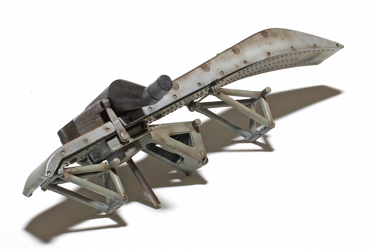
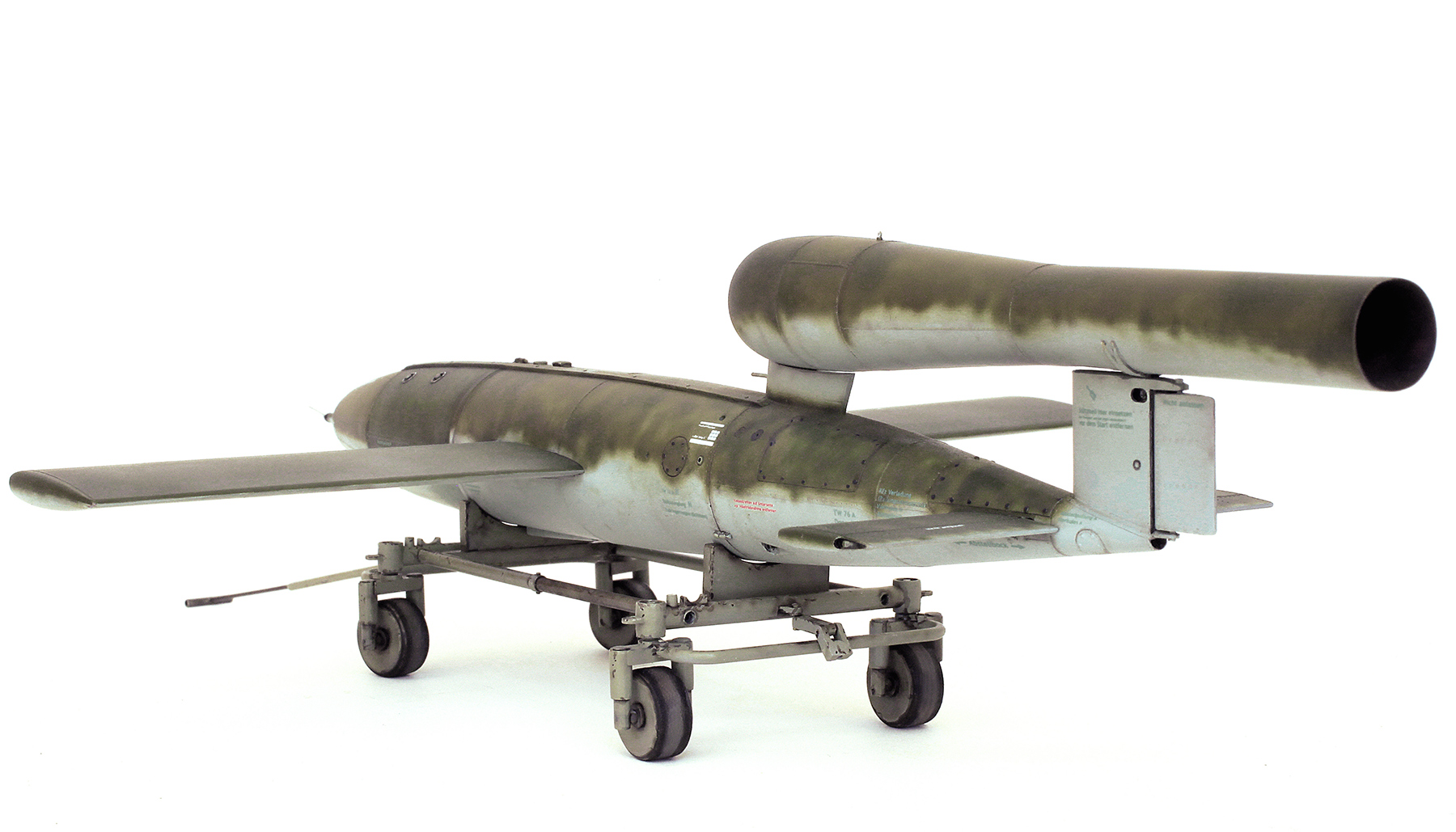
The completed TW-76 transport trolly. Lots of extra details were added to this which included lots of bolt heads, wheel axles, steerable front wheels and a new telescopic towing handle.

Construction complete and waiting for paint.

Transportwagen 76 finished, painted and weathered and with new handle added.
GALLERY


A late inclusion. This shot of the undersurfaces shows that the section holding the warhead was obviously manufactured and painted in a different facility. This is a common feature and can be seen in quite a few subject photos.
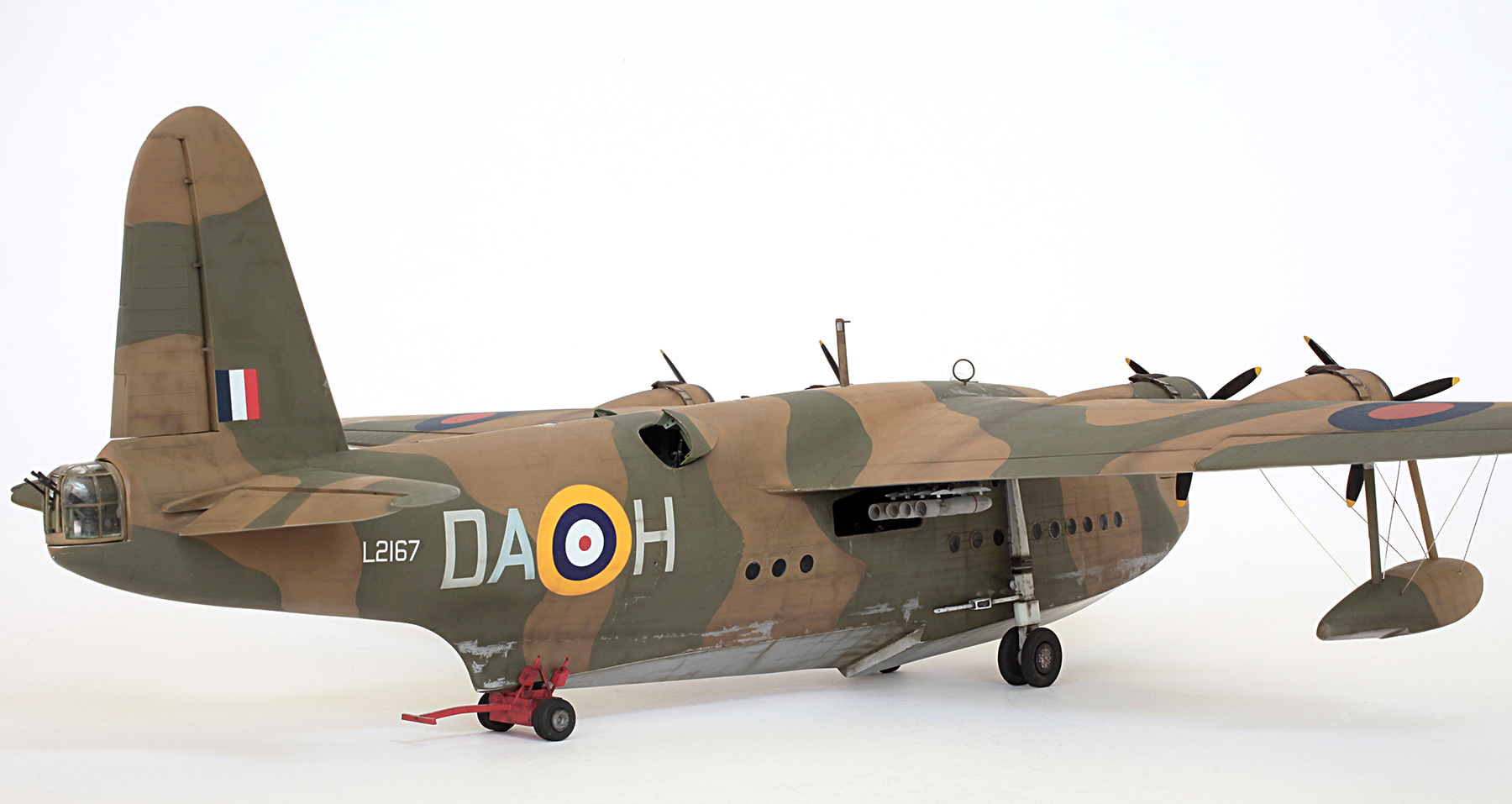
Airfix 1/72 Short Sunderland Mk. III (converted to a Mk. I)
SHORT SUNDERLAND Mk. I

On the afternoon of April 9th 1940 this aircraft from No. 210 Squadron RAF took off from Invergordon, Scotland to make a reconnaissance flight over the Oslo area of Norway to gather information on German movements after their recent attack. They were quickly spotted by the Germans at the captured Fornebu Airport, near Oslo, and from there two Messerschmitt Bf 110’s of 1./ZG 76 were scrambled to intercept. The pilots of the 110’s were Staffelkapitän Werner Hansen and Leutnant Helmut Lent. Lent later became a highly successful night fighter ace. The two shot down the Sunderland with Hansen receiving credit for the victory. All but one of the Sunderland’s crew were lost in the action which sadly included my best friend Bill Young’s uncle, Sgt Pilot Jack Clifford Carpenter. Bill has made a documentary called ‘A Very Short War’ about this event which has been screened several times over the years on Australian television and is really worth a look if you get the chance.
I have done a little bit of photoshopping to this pic. I’ve made the props look as though they’re spinning and, if you look closely, you can just see Uncle Cliff having a quick look at us from the navigator’s astrodome.
The conversion from a Mk. III to a Mk. I
The first step in this conversion was to backdate the later smoother planing hull bottom to the earlier stepped design. Unfortunately I was so consumed when carrying out this work that I forgot to take any W.I.P. photos. All I can say is that it turned out to be easier than I thought thanks to the thickness of this old kit’s plastic and after a fair bit of cutting, filing and sanding only a few areas needed filling with plastic card and a bit of putty. This was all done before the fuselage halves were glued together but they were frequently dry fitted through the process to assure the proper alignment of my work. Well, near enough anyway. I did do it all by eye.

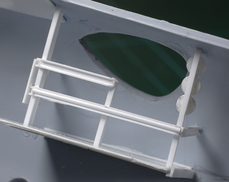
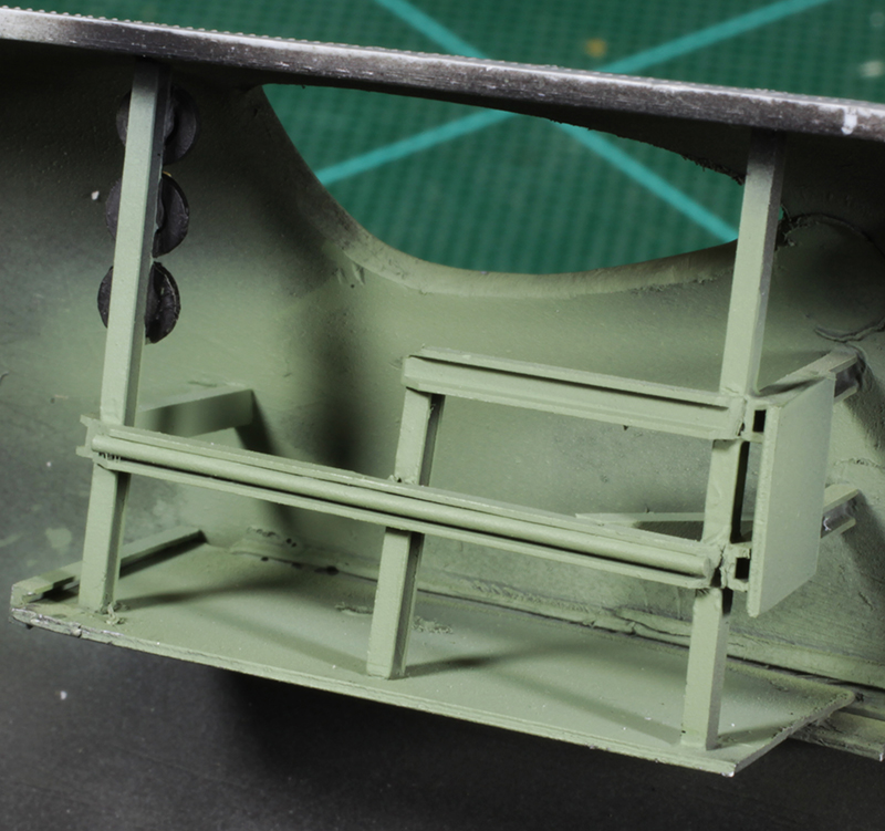
Next step was to cut the two teardrop-shaped holes for the mid upper gun positions. Some internal detail was added using Evergreen plastic rod, card and shapes. There is some really good photographic reference of this detail if you wanted to go nuts but I chose to keep it fairly simple.

Painted interior green with the spare K gun mags painted metallic black.
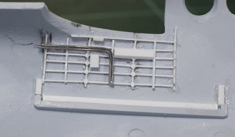
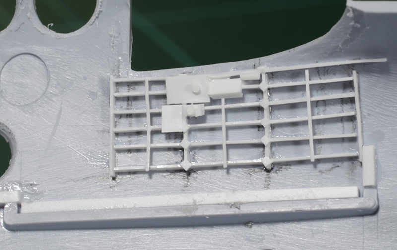
Some detail added to the cockpit side walls again using Evergreen rod and strip and some fine solder wire. Also note that plastic strip has been added to the top of the mounting rails for the cockpit floor. This was done to raise the main interior to a more accurate level.

This detail will never be seen but I know it’s there and now so do you.

I did go a bit overboard with the main cockpit detail but it was quite a lot of fun to do.

Instrument panel and throttle quadrant. The instruments are from an old 1/72 P51 decal sheet with multiple sets of markings. Decals for two panels were cut up to fit the space.


Painted with safety harnesses added. The Sutton harnesses were cut from 0.13 Evergreen plastic sheet which is quite malleable as long as it’s not too old.

Installed.
Bomb aimer’s window. The rectangle of white plastic should be clear. I’ll paint it to look that way later.

A new front door was cut from plastic card and glued over the very faintly moulded kit detail. This shot also shows the round Tamiya tape masks covering all the hull windows. The kit windows are too large so the masks were cut about 0.5 mm smaller in diameter. I think they should be even a bit smaller than that.

The dorsal cut-outs and the top turret hole filled. Also note the small, round observation windows cut into the spine. These were painted black and a corresponding disc of clear acetate was added after the main paint job was done.
The covers for the dorsal gun positions cut from 0.25 mm plastic card.
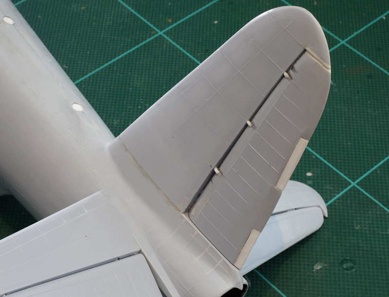
Some hinge and trim tab detail was added to the rudder.

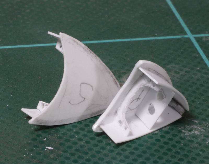
The nose turret needed beefing up. This was done by covering the entire kit part with 0.5 mm plastic card and sanding it to the right shape.

These are the two Vickers K guns for the upper fuselage cutouts. They are made from various bits of Evergreen rod and strip with gun sights made from very fine wire. They are very small.

The quad Browning for the tail turret and the single Vickers for the nose. I did manage to snap the barrel off the Vickers gun pretty early on, so I replaced it with a much sturdier metal version.

The metal version.

Guns and covers in place and a bit of the interior is just visible.

The kit’s prop blades were added to new, more accurate hubs and much stronger shafts.
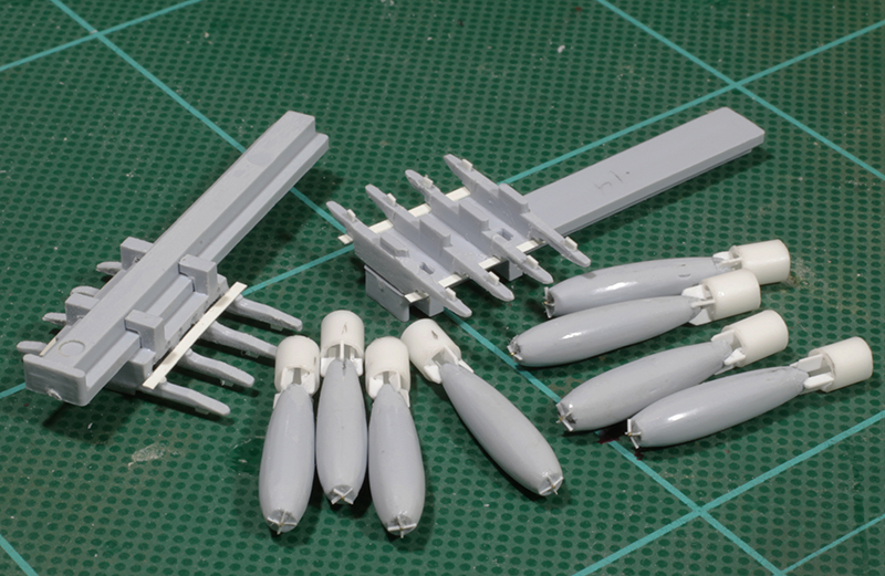
The bombs and bomb racks with a bit of extra detail added.

Bombs painted and ready to be attached to their bomb racks.

The tail’s beaching trolley with a bit of extra detail added.
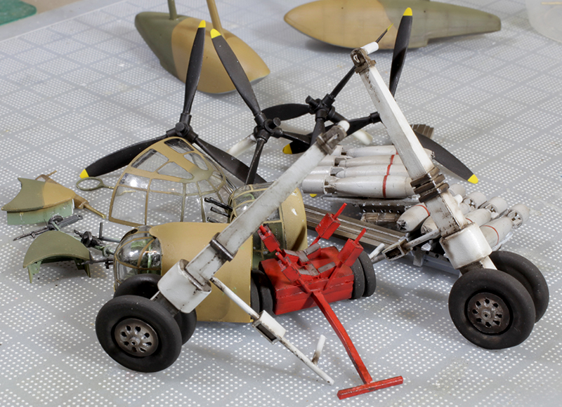
Most of the fiddly bits painted, weathered and ready for installation.

Painted, weathered and waiting for decals (thanks Brett). This shot also shows the more accurate early engine exhausts which I made using 2.5 mm plastic rod. It was at about this point of the build that I realised the kit did not include the Pegasus engines’ supercharger intakes. So I made four by cutting up a row of 1/32 Me 109 exhaust stacks that I found in my spares box. I reshaped them a bit, attached one under each engine cowl and painted them silver. Looks a lot better than nothing.
GALLERY


Hasegawa 1/32 Messerschmitt Bf 109 G-6
THE BLOND KNIGHT

Messerschmitt Bf 109 G-6 as flown by Lt. Erich Hartmann, Staffelkapitän of 9./JG 52, Russia, October 1943.

I completed this model about 20 years ago and thought it was about time for a revamp. This was achieved mainly by tidying up and redoing the main weathering. The wing roots were first to receive attention. A thin, patchy spray of my red-brown mix was applied to replicate exhaust staining and general grime. When this had dried completely the scratches and rivet details were added using a very sharp PRISMACOLOR silver pencil.

The starboard side didn’t receive as much scratching but I did add a bit more exhaust staining and a scratch-built starter crank handle. Also visible in this shot is the open canopy restraining wire which is part of the original build.

High shot showing cammo and weathering. Not sure why the faint, skinny crosses were sprayed in the centre of the upper wing national markings. Perhaps they were applied as an aid for the original painters to align the stencils when they sprayed the main markings. As I said, I’m not really sure but this feature is quite visible in the famous picture of Hartmann leaning against the port side of this plane.

Some extra grime was added to the under surfaces as part of my refurbishment.
GALLERY