STATIC CAPITAL
Chris Wauchop Scale Models and Photography
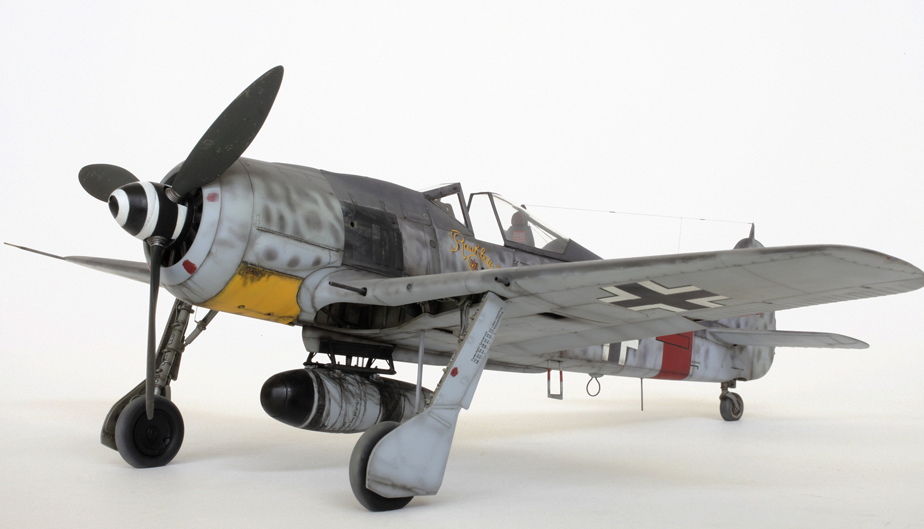
Hasegawa 1/32 Focke-Wulf Fw 190 A8 R2
RAMMJAEGER

Focke-Wulf Fw 190 A-8/R2 as flown by Leutnant Klaus Bretschneider, 5./JG 300, Erfurt, Germany, October 1944.

I made this model 18 years ago, and since it has only appeared on Brett’s web site (in relatively small format photos) I thought it was time to re-photograph it and post some much larger, more detailed images here. I have done a bit of a clean up of the model, and since more pics have come to my attention, I corrected some of the paint work and weathering. This includes a more accurate spinner spiral, paint chipping and dirt on the wing roots and under surfaces. Also in one photo of this plane I think it shows that the radio antenna wire retraction mechanism was disconnected and so, with the canopy open, the wire is just hanging slack. But as I had fixed the canopy so well, and I’m not 100% sure about this detail, I decided to leave it as is.

More dirt and chipping on the starboard wing root.

Extra soot around the shell ejection chutes and along selected panel lines on the belly.
GALLERY


ORIGINAL ADDITIONS AND ENHANCEMENTS
- Before construction commenced rivets were added to the exterior surfaces.
- The kit-supplied belly tank was replaced with the more correct part from Hasegawa’s Me 109 G6 kit. Plumbing, stability pins and braces were added to the tank and the mounting rack using brass wire, plastic rod and stretched sprue.
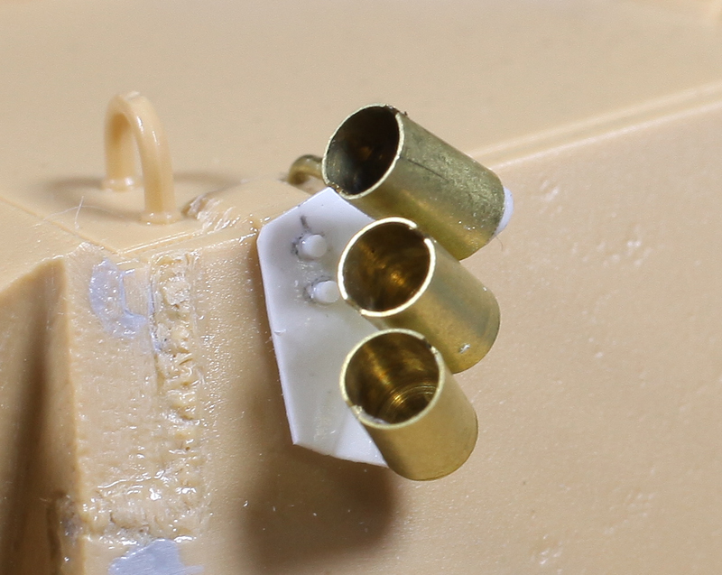
- The 30mm shell ejector chutes on the lower wing were cut open and the outer 20mm chutes were closed off.
- Brass tube was added to the wing leading edges to represent the 30mm cannon barrels. The tips of the kit’s plastic 20mm cannon barrels were hollowed out using the point of a new scalpel blade.
- All tyres were flat spotted and the tail wheel structure was modified so it would sit in a slightly more retracted position.
- Plumbing and wiring was added to the main undercarriage legs and actuator arms using lead wire and fine copper wire.
- The tailwheel retraction wire seen attached to the starboard undercarriage retraction arm was made from stretched sprue.
- Flaps were modified so they would sit in a more realistic 2/3rd closed position.
- The kit’s thick plastic D/F loop was replaced with a metal staple that was straightened and then bent to shape.
- The plastic FuG antenna mast was replaced with a piece of finer diameter brass wire cut to the appropriate length.
- The whip antenna wire at the end of the Morane mast was replaced with much finer brass wire.
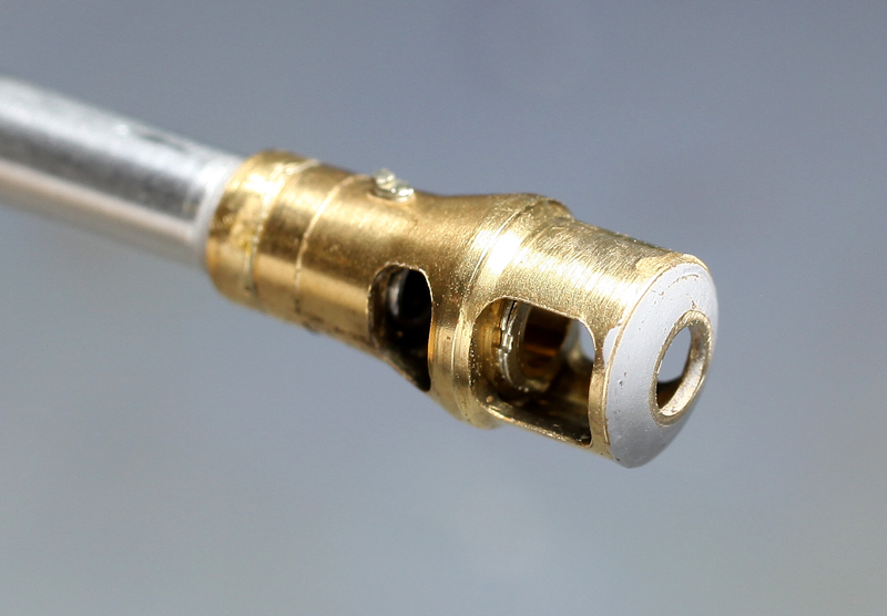
- The pitot tube was replaced with Albion Alloys telescoping brass tube.
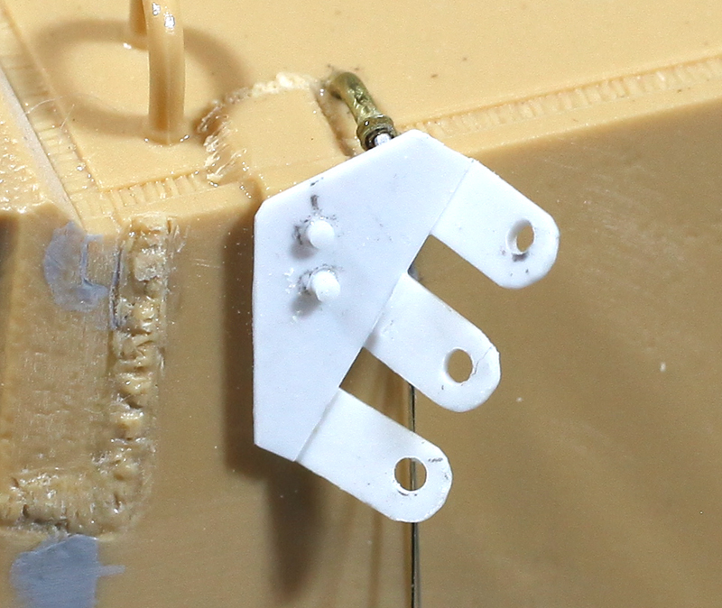
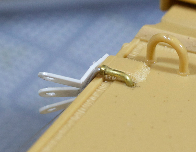
- Landing gear retraction indicators were added to the top of the wings using fine brass wire.
- Armour plates were added to the fuselage sides below the windshield and the cockpit. These were cut from .020″ plastic sheet and had all their edges bevelled as per my reference pics.
- The cowl gun troughs were filled with pieces of shaped plastic rod.
- Bracing wires were added to the back of the armoured headrest using black nylon mono filament (invisible mending thread).
- Finally the radio antenna wire was added. Before the rear canopy section was attached a small hole was drilled in front of the aerial pulley wheel housing and a longer than needed length of nylon mono filament was threaded through. The end was then fed through a hole that had been drilled in the centre of the bracket plate at the rear of the canopy combing and glued in place. A tiny hole was drilled down into the top of the aerial attachment spigot on the vertical tail fin and a small loop fashioned from very fine wire was super glued into it. After the rear canopy was firmly fixed in place the thread was pulled tight through this loop, tied off and permanently fixed with a drop of super glue.
Revell 1/32 Me262 A-1a
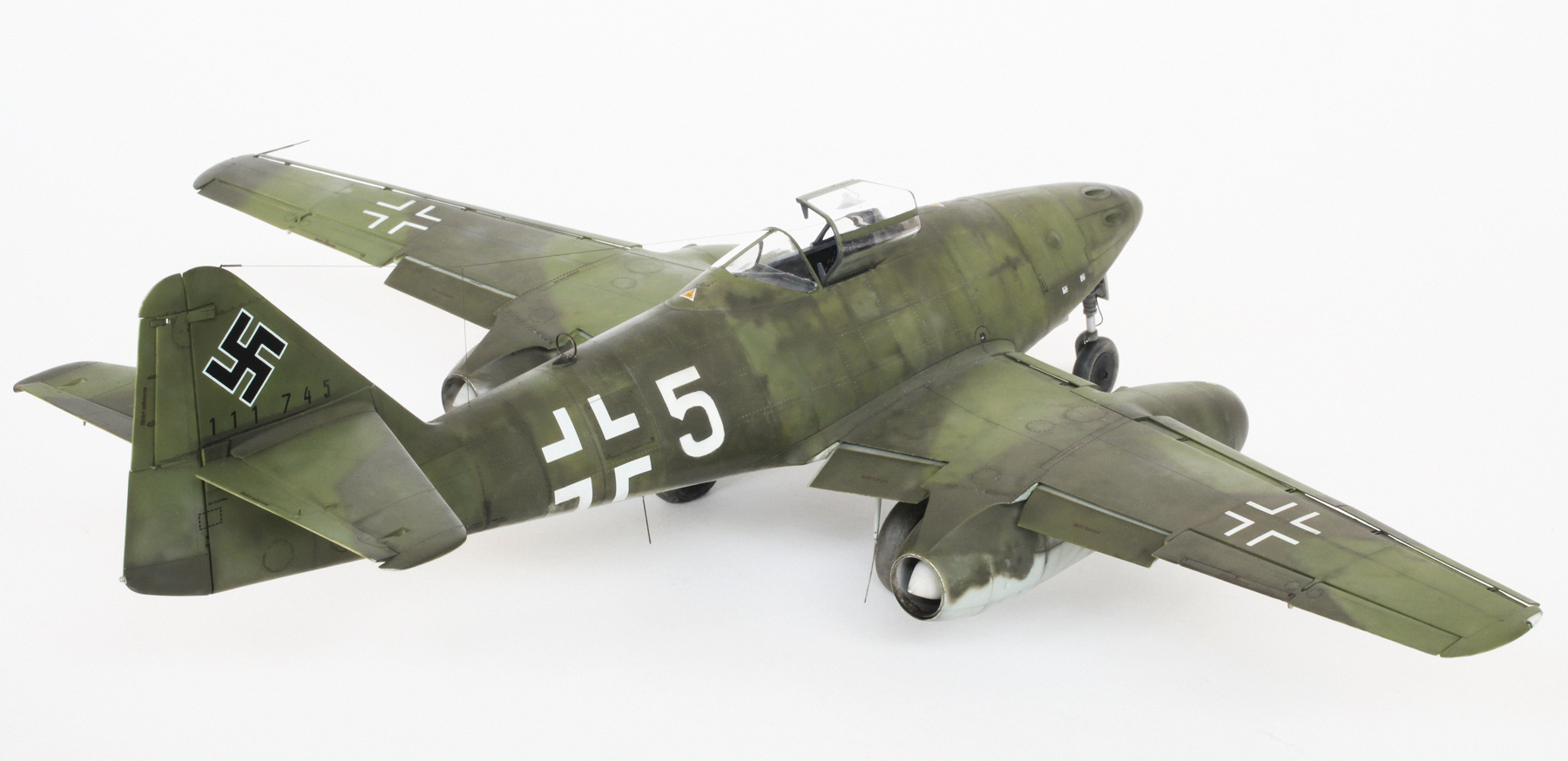
Me262 A-1a SCHWALBE

Messerschmitt 262 A-1a flown by Unteroffizier Eduard Schallmoser, JV 44, München-Riem, Germany, April 20, 1945. Schallmoser was flying this aircraft when he accidentally rammed a P-38 Lightning, slicing its complete tail assembly off with the jet’s starboard wing. Sustaining only light damage, Schallmoser was able to return to base and land safely but I’m not sure whether this aircraft ever flew again.

The seat’s leather cushion was first sprayed matt orange and then carefully shaded with a thin mix of red brown. The deeper creases were then shaded with my black/brown mix. Cracks and scratches were brush painted using straight black and a lighter shade of the original orange. Once dry the cushion was rubbed with my greasy fingertip to give it the leathery sheen. Small wire loops were added to the top of the seat back as attachment points for the safety harness.

Cockpit interior waiting for the addition of instrument panel and safety harness.

Toe straps were added to the rudder pedals. These were made using thin strips of lead foil.

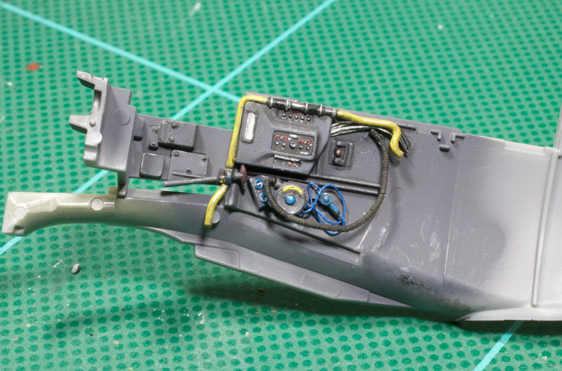
Lots of wiring was added to the back of the instrument panel using various gauges of lead wire.

As I was not sure how much of the wiring was going to be visible it only received a rough coat of yellow. Each separate instrument dial was cut from various decal sheets and added to the individual bezels after the complete panel had been painted.
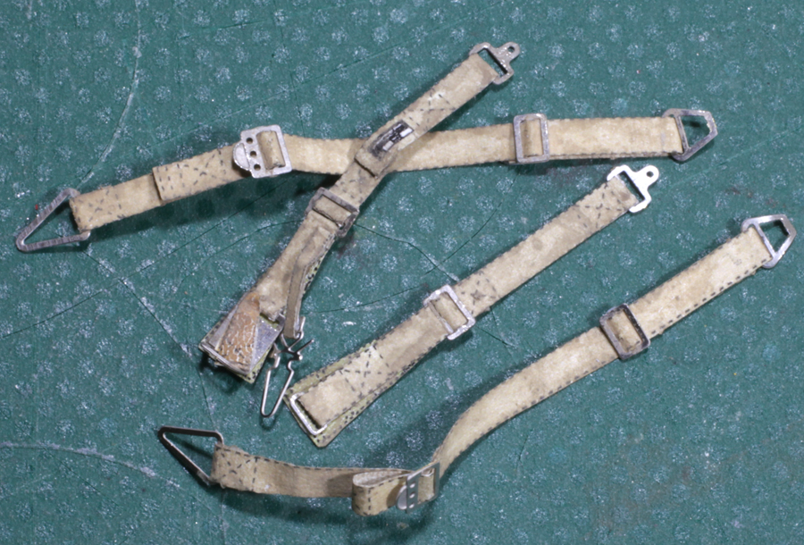
HGW’s Micro fabric seatbelts and P/E buckles assembled and weathered.

Cockpit tub ready for instillation.

Underneath the cockpit tub with lots of wiring detail added. This area will be visible through the landing gear openings.

The kit’s ring pull handles in the tip of the bullet-shaped Riedel starter engine fairings were removed and replaced with finer scratch-built items.

A push rod was added to the rudder’s offset trim tab using fine brass wire.

If you do not want to build your model with open gun bay and engine cowlings then a fair bit of filling and sanding will be necessary because of the rather poor fit of these parts. Also I was not happy with the uneven contours around the front end of the nose and, again, a lot of filling and sanding was required to make this area look right. The tips of the cannons’ blast tubes were also added.

The emergency canopy release handle was added. This was made from Evergreen plastic strip that was cut and bent to shape.

Initial application of camouflage complete. The colours look very bright in these shots but once matted down and weathered the vibrance was reduced considerably. Also visible in this and the next couple of shots are rows of rivets that were added to the fuselage. I didn’t do any on the wings due to a severe lack of motivation.

Gloss coated with decals applied. The W.Nr. on the vertical tail was made using individual numbers cut from several different decal sheets.

I could not find a decal to match my reference for the tactical number ‘5’ so I drew it free-hand and scanned it into the computer and printed it to the correct size onto self adhesive paper. Using a new very sharp scalpel blade, masks were carefully cut out and the number was sprayed on both sides of the fuselage.
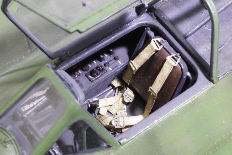
Cockpit interior complete.

In this shot you can see the tiny brass wire hook holding the radio antenna wire, the safety wire holding the open canopy, the locking handle on the inside of the port canopy frame and the grab handle on the inside of the canopy centre frame.

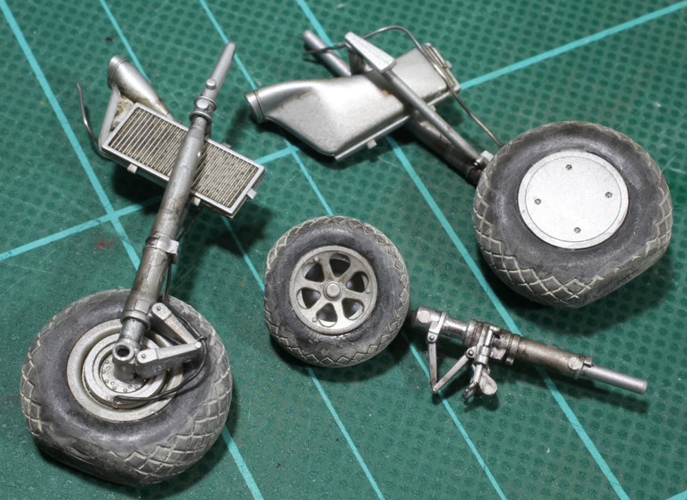
All the dangly bits ready for installation. Lots of detail added to these parts including hydraulic and pneumatic lines, a new DF loop made from scrap P/E bent to shape, and the brass wire end on the FuG-16ZY antenna mast which is lying on top of the new pitot tube made out of telescoping brass tube. Also note the authentically hand-painted No.5 on the front nose gear door.
Gallery


Tamiya 1/48 P-38G Lightning
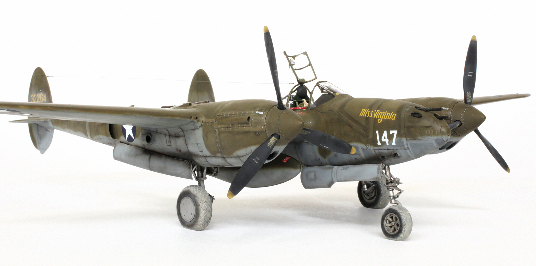
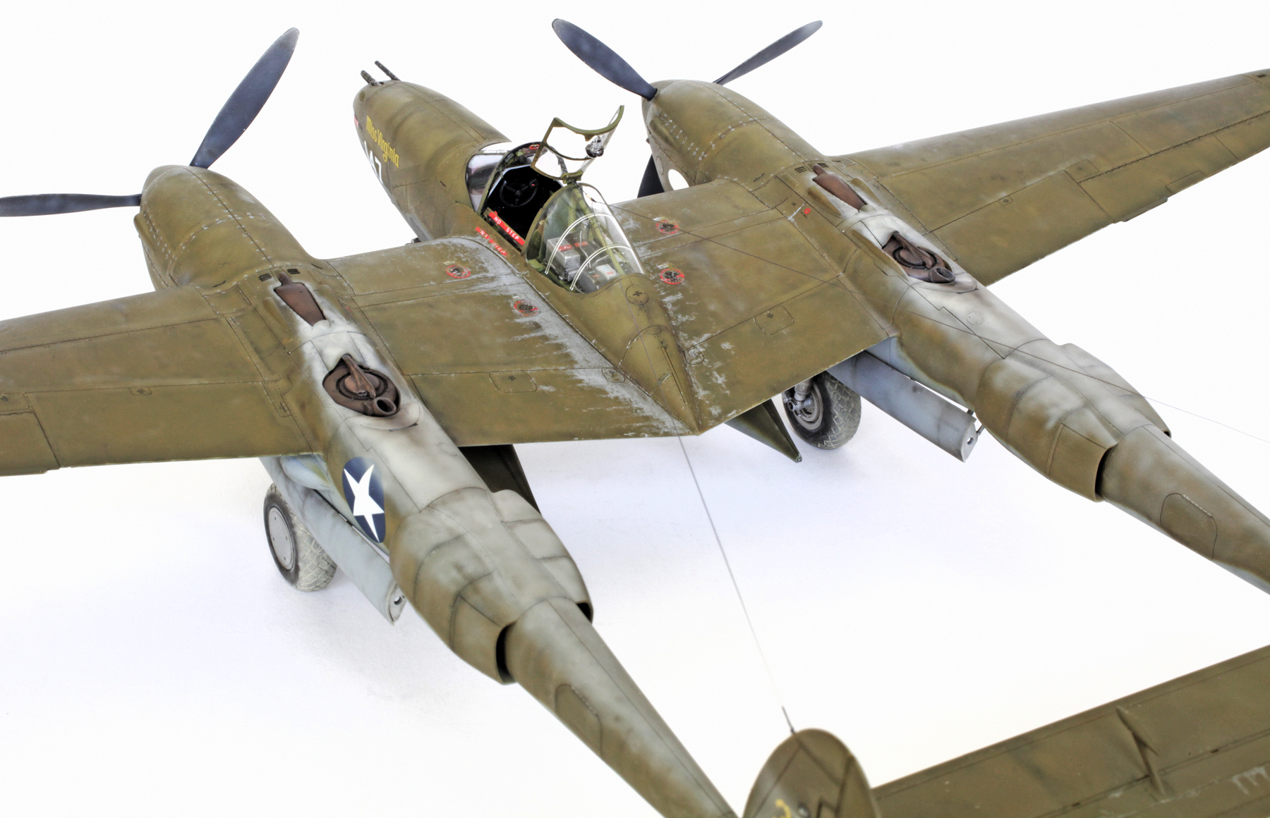
LOCKHEED P-38G Lightning

This P-38 was assigned to Capt. Bob Petit of the 339th FS/347 FG while operating from Kukum Field on Guadalcanal in 1943. On April 18th of that year Lt. Rex Barber flew this aircraft while taking part in Operation Vengeance. This was the mission to intercept the Japanese flight carrying Admiral Yamamoto. The flight was intercepted over Bougainville Island where Lt. Barber successfully engaged and shot down the G4M ‘Betty’ bomber carrying Yamamoto who was killed in the ensuing crash.

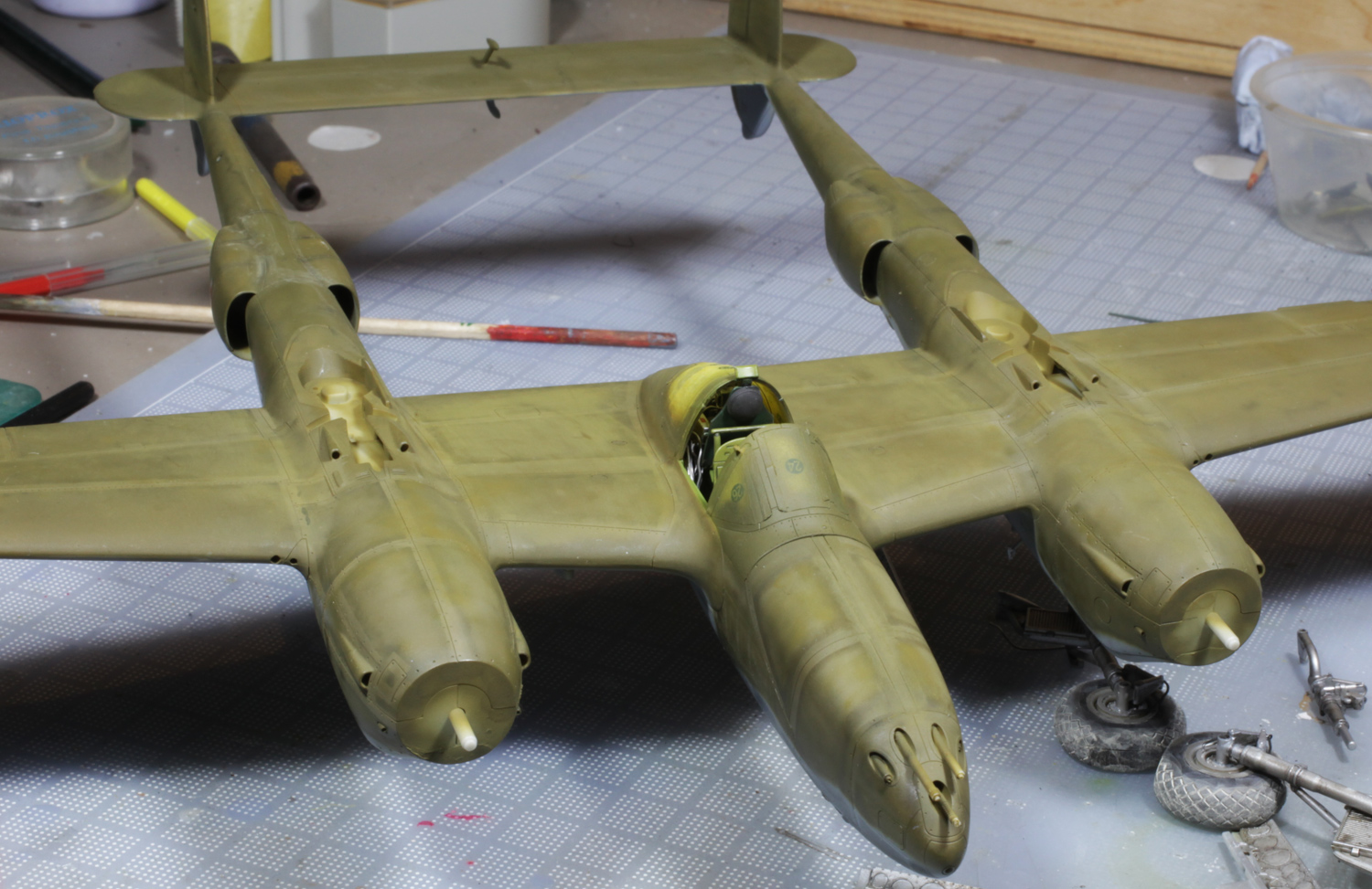
The main assembly of this kit was done by Brett Green. My work started with the painting and addition of wiring to the radio gear using 0.2mm and 0.3mm lead wire.

Red and blue placards were carefully painted on.

In place behind the pilot’s seat.

The super charger/exhaust units. These were first painted silver then sprayed blackish brown. They were then shaded with blacker brown and given a black wash.

Drop tanks painted and weathered.
Undercarriage was first painted silver then given a dirty black wash. Careful shading was then applied using the airbrush. Note also the addition of hydraulic brake lines.

Gear doors were painted silver on the interior and neutral grey on the exterior and then given the same treatment as above.
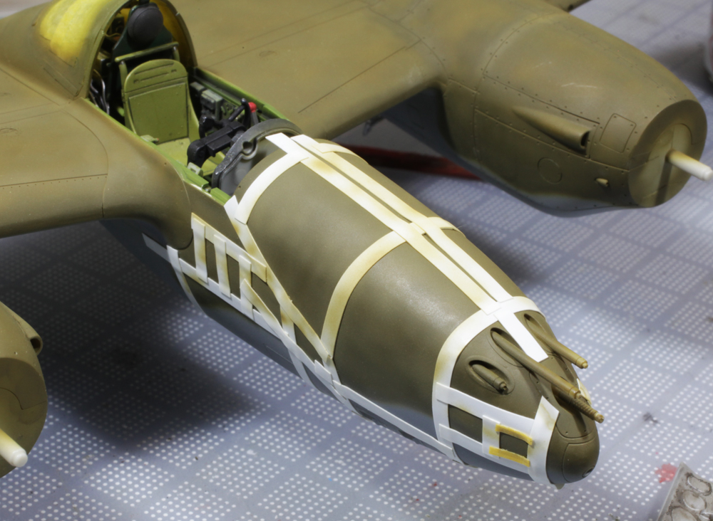
When these aircraft were shipped overseas certain panel lines were sealed with tape. To replicate the effect left after the removal of this sealing tape, the appropriate panel lines were first sprayed with a lighter version of the main cammo colours and then covered with Tamiya’s 2mm flexible masking tape. Various darker versions of these cammo colours were then sprayed along the edges of the tape.

When the tape was removed the resulting effect was pretty close to my reference pics.
The main colours were then mottled with varying shades of themselves and my black/brown mix.
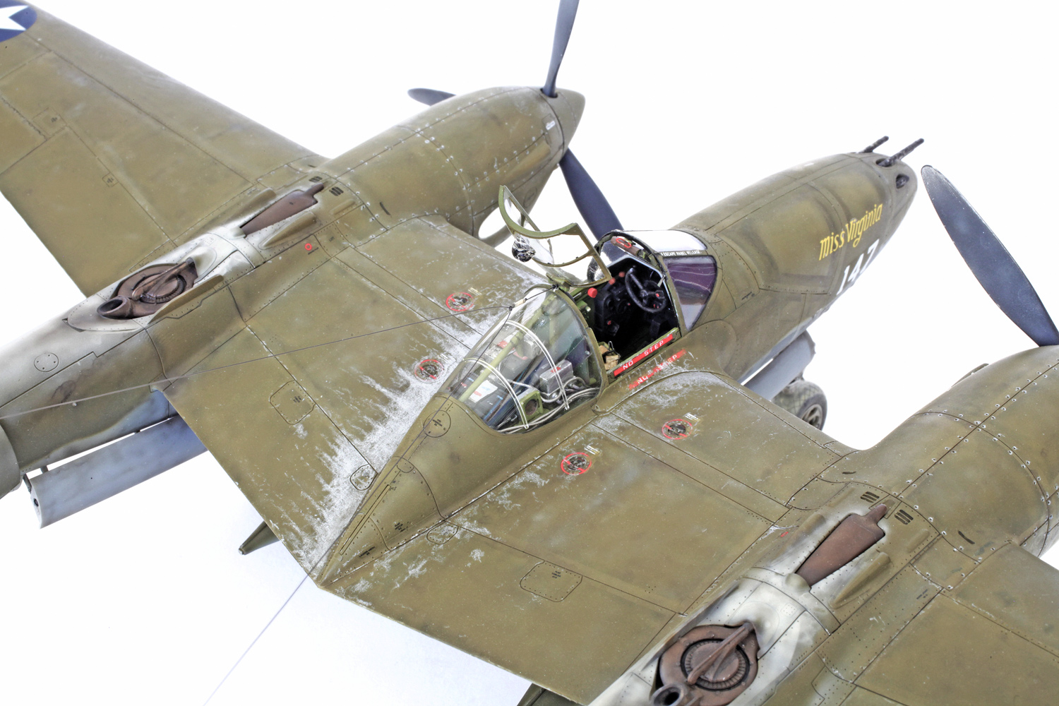
This and the next shot show various weathering effects including lean exhaust staining, paint mottling and chipping.

The paint used for the exhaust stains is Tamiya XF-55 Deck Tan. The paint chipping was achieved using a very sharp Prismacolor silver pencil.
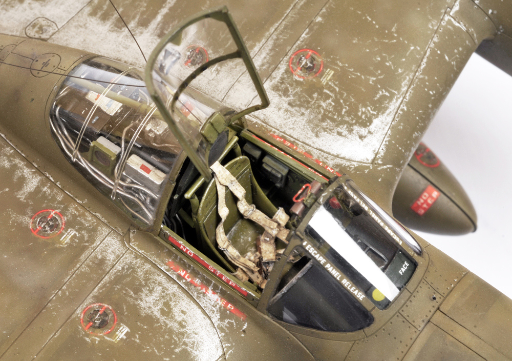
This shot shows my scratch-built safety harness made using lead foil and fine wire. Also seen attached to the top of the windscreen frame is a small red handle. This was made from the same fine wire as the safety harness buckles and, I think, in reality it was used to adjust the rear view mirror when the canopy was closed. Or I could be completely wrong.

Sealing tape, gun dust and paint chipping effects can be seen in this shot.

Exhaust staining on the tail fins.

Brett’s fantastic compilation shot. Ready for Operation Vengeance.
GALLERY


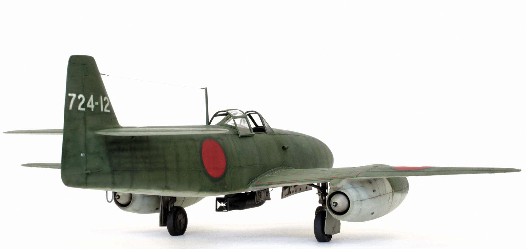
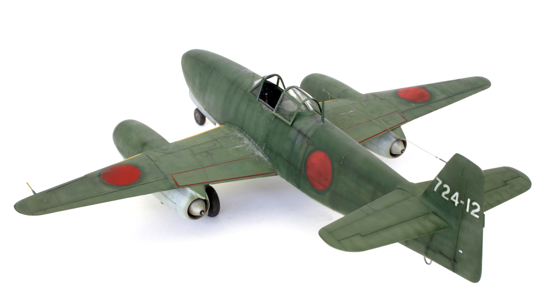
FineMolds 1/48 Nakajima Kikka (2019 refurbishment of 2007 build)
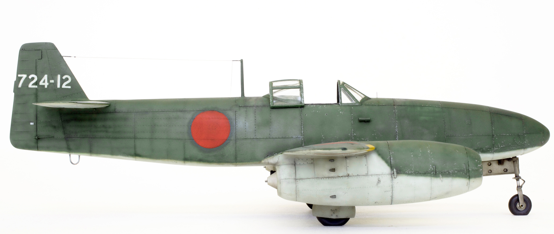
NAKAJIMA KIKKA (Orange Blossom)

The Kikka was intended for use in suicide missions and only received a name and not the letters and numbers usually designated to I.J.N. aircraft.

My original 2007 build. This was done mainly out of the box with a few alterations and additions. The main alteration was to open the kit’s one-piece canopy. To achieve this the kit part was carefully cut into three sections and the centre section was then used as a plug to form a new, thinner part by plunge moulding a heated piece of acetate over it. The original canopy frames did not mould clearly so new frames were cut from plastic strip and very carefully glued in place using super glue.

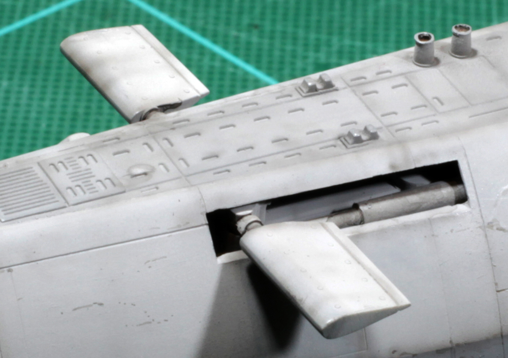
Some extra detail had been added to the undercarriage and bomb in the original build. These included brake lines on the main gear legs, the inner gear door closing brackets and a fusing prop on the bomb’s nose.

Refurbishment work began with the removal of the fuselage hinomarus and the addition of canopy rails to the top of the cockpit side walls.

Wing markings were so well fixed to the original paint that I could not remove them so after a light sanding they were left in place and then painted over.

As I didn’t have any appropriate decals to replace the tail codes these were also left in place and carefully brush painted around and over. The RATO pods (one of which can be seen in this and the previous shot) were later removed as I didn’t think that an operational aircraft would have carried them in this position. And as I did not have any information to tell me where else they might have been placed they were left off. In later shots you can see that I also added rivet detail to the lower engine cowls.

In the original build I did add a fair bit of extra detail to the cockpit interior including seat belts and various levers and handles using stretched spru and lead foil. Some of these additions can be seen in this shot of the finished model.

Original paint and markings.

Now with new paint and markings the plane looks as though, in reality, it had been very hastily painted and looks much rougher and, I think, more realistic than my original scheme.
GALLERY


Revell 1/144 Type XXI U-Boot
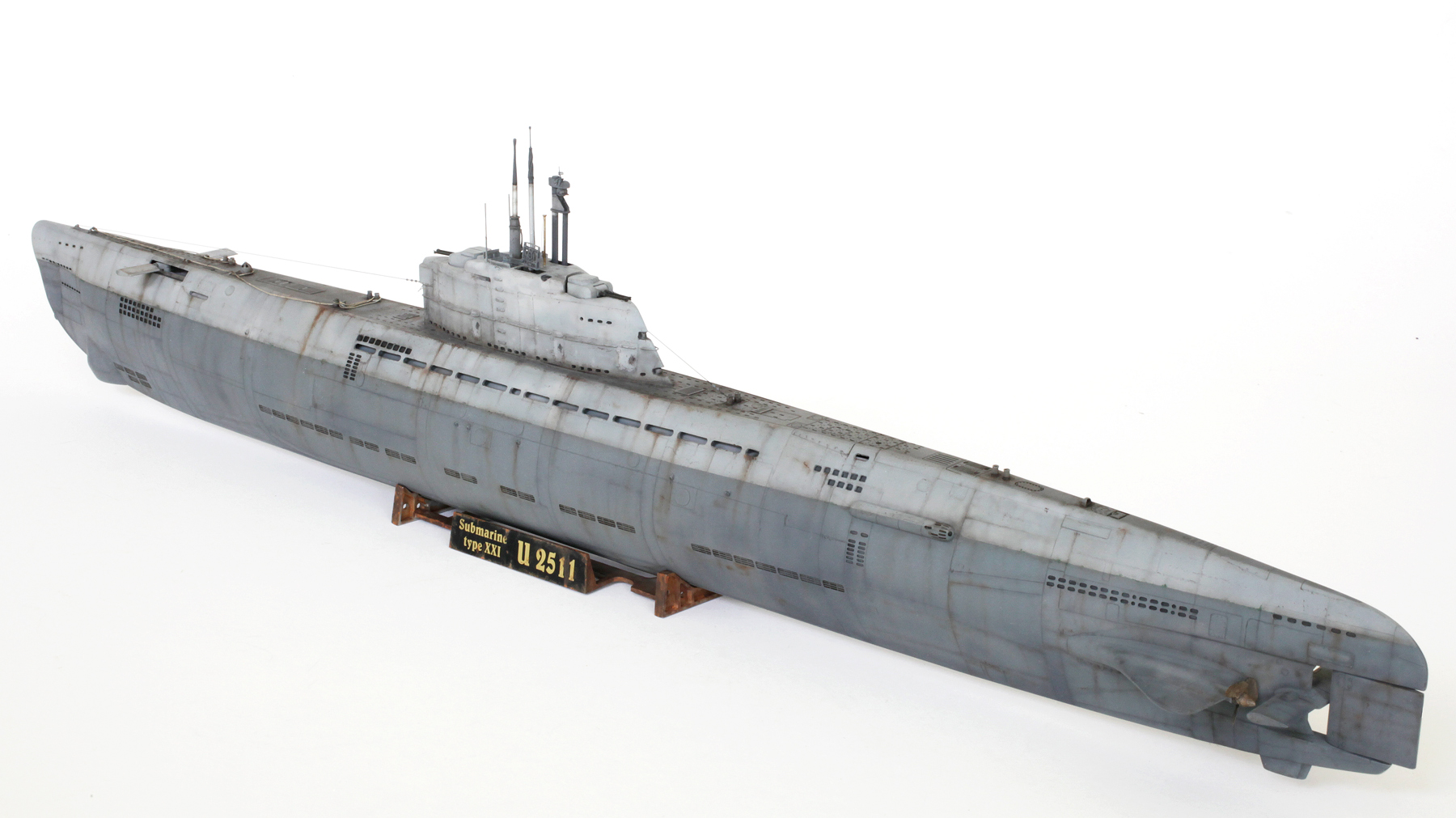
Kriegsmarine Type XXI U-Boot 2511

U-2511 was built at the Blohm und Voss shipyards Hamberg and launched on the 2nd of September 1944. She was commissioned on the 29th of September ’44 under the command of Korvettenkapitän Adalbert Schnee. After initial training U-2511 was transferred to Bergen, Norway from where, on the evening of the 30th of April ’45, she set sail for the Caribbean on her one and only patrol. On the 4th of May, with a British cruiser in his sights, Schneer received the end-of-the-war cease fire order. He claimed that he made a practice attack on the British ship before escaping undetected. On the 7th of January 1946, U-2511 was scuttled by the British off the northern coast of Ireland where she still lies, relatively intact, today.

I decided to add as much extra detail as I could in this small scale. This began by cutting out the main ballast vent holes and glueing a strip of styrene card behind them at about a 45 degree angle.

Next, the forward dive plane actuating cylinders were added. These were made using 2.5mm and 1.6mm Evergreen plastic rod.
These cylinders are quite visible if the model is displayed with the dive planes extended. Also in this shot can be seen the early detail added to the top of the deck bollards. Handles were added to the hollowed out tops later.

The kit’s solid moulded hand rails and ladder rungs were removed and replaced with 0.3mm brass and copper wire.

Access doors and nav lights were detailed using 0.25mm plastic card.

After these photos were taken the row of vent holes directly under the hand rail and the first three rows above the rear section of rail were filled according to my reference.

The crew access hatches were cut open and internal detail was added using plastic card.

Holes were opened up so periscopes, schnorkel and other detail could be fixed in more realistic positions.

The kit periscopes were replaced with scratch-built items. This is the night periscope made by shaping a piece of 1.6mm Evergreen plastic rod using the grinding stone attachment on my motor tool.

The attack periscope was made using the same 1.6mm rod and detailed with stretched spru and brass wire.

The kit D/F loop was replaced with a scratch-built item made using brass rod and copper wire.
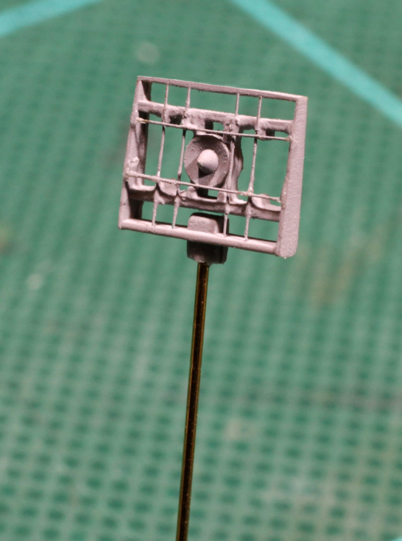
The kit Hohentwiel radar antenna was detailed with 0.1mm brass rod.

The conning tower with most of the extra detail added. The schnorkel was extensively detailed using plastic card of various gauges and the night periscope housing tube, made out of 3.2mm plastic tube, was added. The kit antenna masts were replaced with items made using telescoping brass tube. After this shot was taken a shaped slot was cut to accommodate the scratch-built D/F loop.
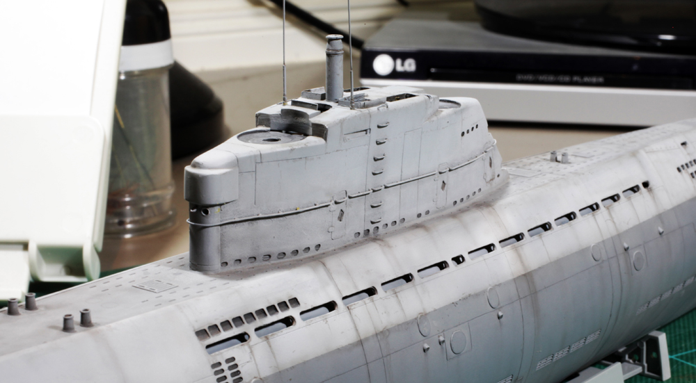
In this shot the sharp edges of the gun turret surround’s rear outer corners can be seen. These were filed and sanded smooth to look more like my reference.

This, and the next shot show the boat’s main colours plus the beginning of the weathering.


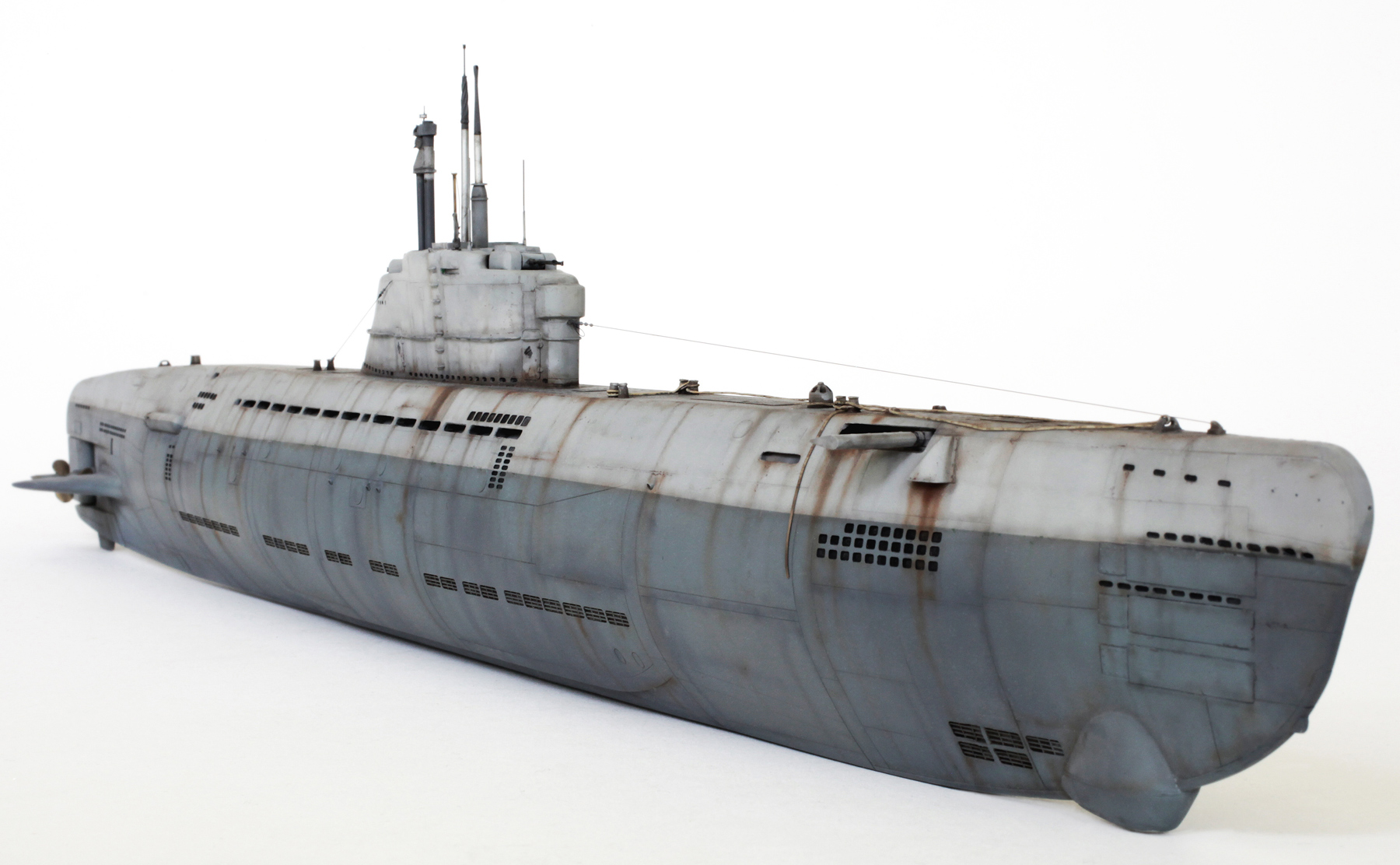
The finished model with mooring ropes added. These ropes are made from fine solder wire. Also note the handles added to the hollow tops of the bollards.

The rounded corners behind the gun turrets can be seen here. Also visible is a flagpole made using Evergreen plastic rod with a stretched spru halyard rope.
GALLERY


FineMolds 1/48 KUGISHO (Yokosuka) D4Y4 Suisei ‘Judy’
KAMIKAZE

Kugisho D4Y4 Suisei of the 601st ‘Special Attack’ FG, Japan 1945

Some extra detail was added to the cockpit interior. This included seat belts from lead foil and various knobs, handles and placards from Evergreen plastic card and rod.

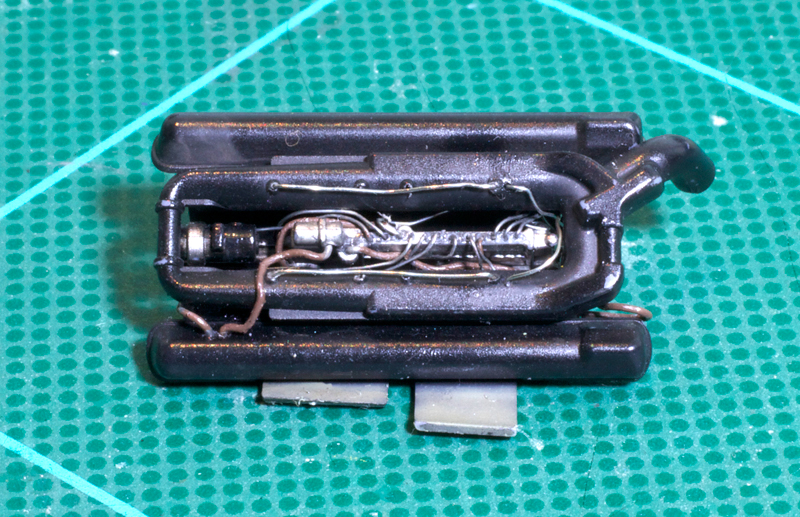
Most of the gear in the rear cockpit has been removed to reduce weight for its one-way mission. An empty radio box was added, instrument housings were drilled out and some loose wiring was added.

After the extra head armour with its support braces and rudder pedal toe straps were added, the interior was given a coat of Tamiya XF-71 Cockpit Green.

Some weathering was done with my red brown/black mix and a Prismacolor silver pencil.

Wiring was added to the cockpit sidewalls using fine wire. A perforated strip was glued to the side of the bomb bay opening after the doors had been removed. The kit’s closed engine cowl cooling fins were cut out and replaced with scratch-built opened ones. Some internal detail, which may be visible, was added. The back of this added detail can be seen here.

Painted and weathered.

Ignition harness and wiring were added to the very basic kit engine.

Detailed and painted. Luckily not much will be visible once it’s behind the big prop spinner.

Detail behind open cooling fins.

Cooling fins glued in place. Exhaust pipe ends have also been hollowed out.

Rivet detail was added to the exterior surfaces using the MDC 1/48th Rivet making tool.

Upper wing rivet detail.
Lower wing rivets. Also three large weight holes were drilled through the rear wheel well wall and small perforated strips were added to the front and rear of the round wheel housing.
Wheel wells and inner gear doors had extra detail added using fine brass and solder wire.
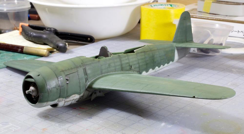
In this shot basic painting is complete and weathering has begun. Undersurface colour is Gunze Sangyo Mr Hobby H61 IJN Gray. Upper surfaces are a mix of Tamiya XF-11 J.N. Green with a dash of XF-12 J.N. Grey added to lighten it up a bit. Selected panel and rivet lines were then carefully sprayed with a very thin mix of straight XF-11 J.N. Green.

All the markings were masked and sprayed before the weathering was added. The main weathering is complete in this shot. The paint chipping was achieved with the use of a very sharp Prismacolor silver pencil. The windscreen and opened sliding section of the canopy were replaced using the vac-form offering from Squadron.
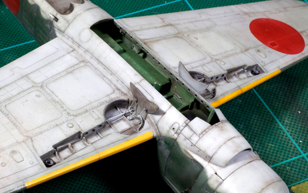
Undersurfaces painted and weathered. This shot was taken mainly to show the finished wheel well detail.

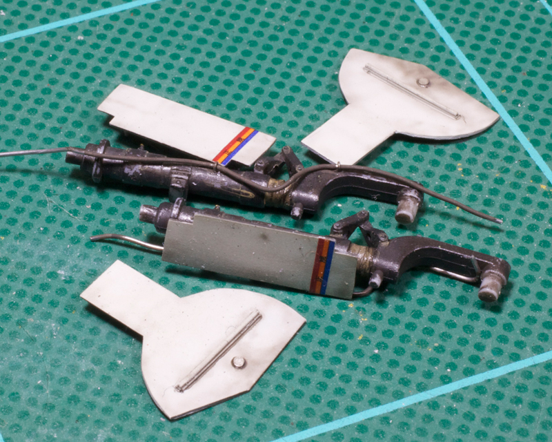
The kit 800kg bomb had extra detail added which included fin braces and a P/E fuse arming prop from the spares box. Not sure what the device strapped to the centre of the bomb is but I made it out of Evergreen plastic and Albion Alloys brass tube to look as close as I could to my reference. A detonation pin was also added to the tip of the nose.

Painted and lightly weathered. The red stripe is pure conjecture on my part.
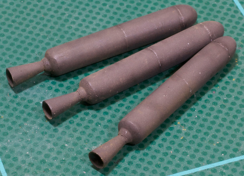
Rocket motors were painted with a 50/50 mix of dark grey and red brown. The inner walls of the exhaust nozzles were thinned by hollowing them out with a motor tool.
Main undercarriage parts detailed, painted, decaled and weathered. Note that the main legs have been shortened by cutting a couple of mm’s from the oleo legs and closing the oleo scissors slightly. This was done to indicate the compression caused by the extra weight of the large bomb and rocket motors being carried. This alteration made it necessary to separate the lower wheel covers from the upper leg covers as in reality the wheel covers would slide up the outside of the leg covers. The kit gear covers were way too thick for this to look right, so the upper parts of the covers were sanded to a better scale thickness. It turned out to be easier to remake rather than to alter the lower wheel covers, so new parts were cut out of 0.25 mm plastic card. Detail was added to the outside of the new wheel covers using plastic strip and rod. Fine solder wire was also used to add brake lines to the undercarriage legs.

Bomb, rocket motors and undercarriage have been glued in place. Also note that the main gear tyres have been flat spotted.

Mounting step and handle were also added. Although they’re not seen in this shot, the plastic pitot tube was replaced with Albion Alloys sliding brass tube and the solid grey plastic tail navigation light was cut out and replaced by gradually building up layers of Testors clear parts cement.
GALLERY


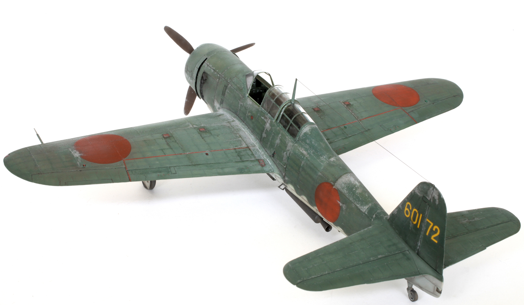


Hasegawa 1/32 P-40E Warhawk (made as a Kittyhawk Mk.1a)

Kittyhawk Mk.1a of 3 Squadron, RAAF North Africa, middle of 1942 as flown by Flt Sgt Lloyd ‘Danny’ Boardman.

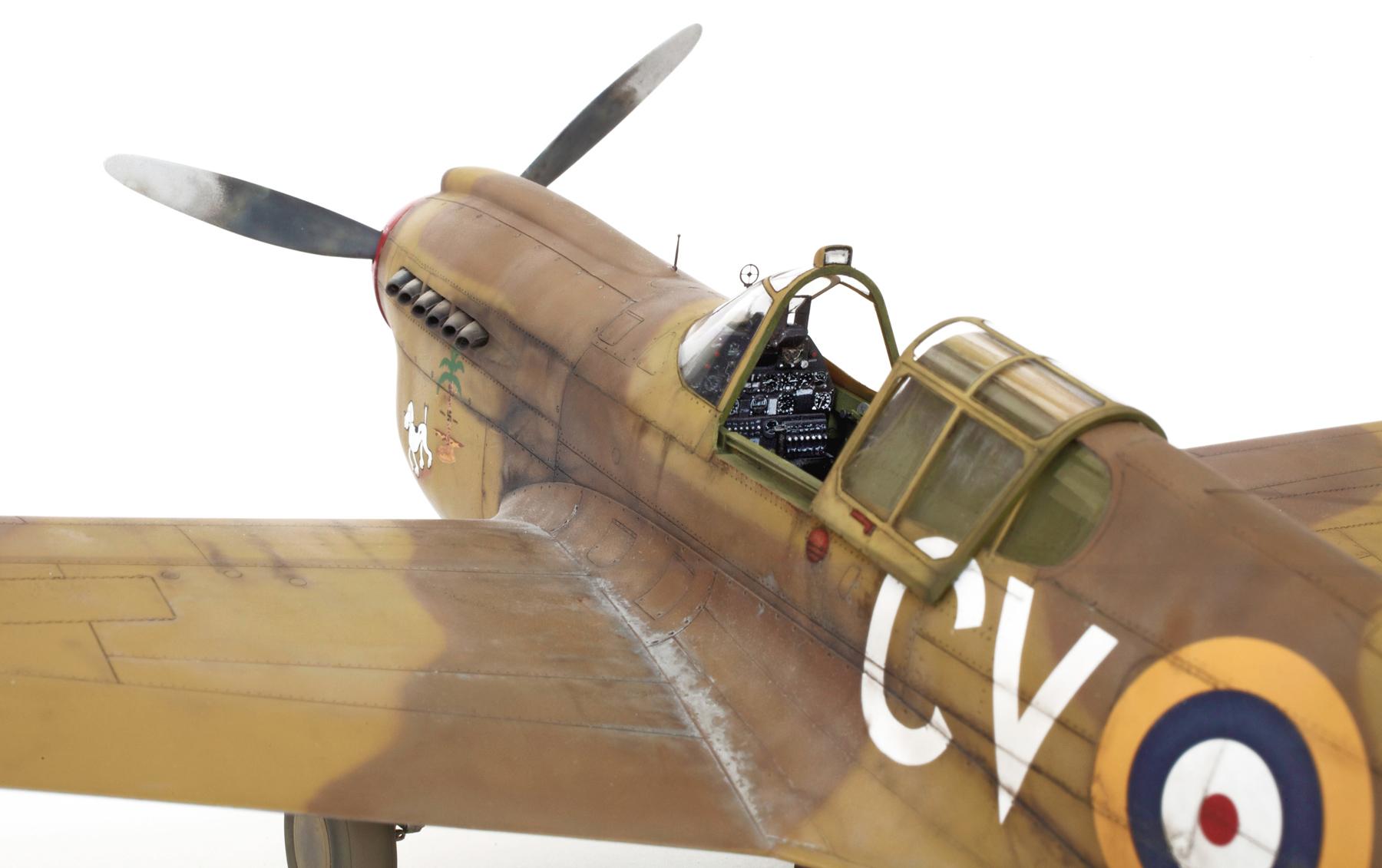
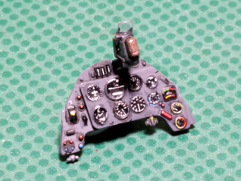
Instrument panel with kit decals. Each instrument dial on the kit decal was carefully cut out and applied separately. The clear reflector element and solid side panels of the N-3A gunsight were replaced with clear cell and plastic card.

Cockpit elements painted and ready to be assembled. The U.S. safety harness is from HGW and probably should be a Sutton Harness as used by the RAF. But this is what I was supplied with and I figure that these aircraft were probably delivered fitted with these belts.

Spinner, prop and undercarriage elements painted and weathered. Note all tyres have been flat spotted and brake lines have been added to the main undercarriage legs.

Undersurface Azure blue is my own mix and isn’t quite as intense as it appears in this photo. Weathering has begun here as well.

Gunze Sangyo H72 Dark Earth and H71 Middle Stone were used for the upper surface colours. Weathering has also begun along panel lines, wing roots and around the gun ports.

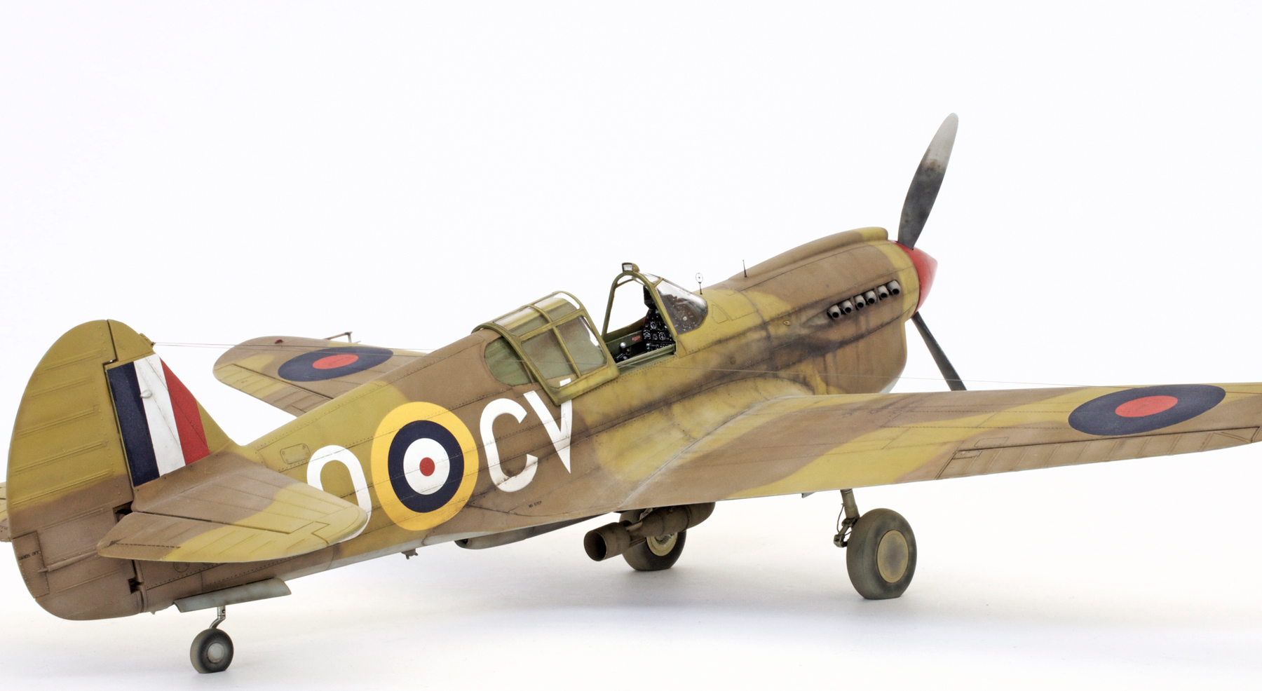
Lots of oil leaks and gun dust as per reference were added using the airbrush and my black/brown mix.

Weathering almost complete. More weathering will be done after decals have been applied.

The main photograph I used for reference shows this plane carrying a 250lb GP bomb fitted with a long detonation pin. Luckily I found that I had couple of 250lb GP bombs in my spares box which were left over from the Tamiya Spitfire I built a few years ago. With the addition of a few scratch-built details one of these would be perfect for the job.

250lb GP bomb painted and weathered. The long impact-detonation pins were fitted to these bombs so that they would explode slightly above ground level therefore causing a much wider spread of schrapnel. Very effective when used as an antipersonnel weapon.

The bomb mounting gear supplied with the kit was unsuitable for this sized bomb so a new rack with sway braces was scratch built using plastic strip, plastic rod and brass wire. Also seen in this shot are the actuator rods fitted to the inside of the undercarriage doors which were also made from fine brass wire.
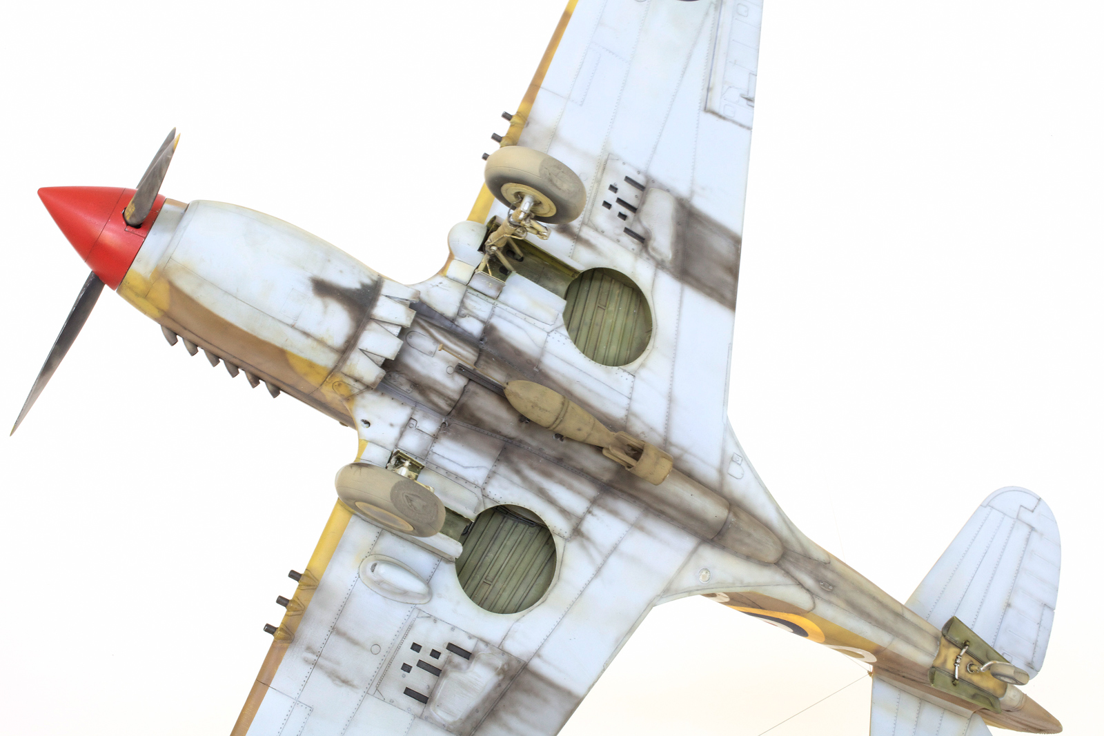
Bomb fitted to the very dirty under belly of this well worn war bird.

This shot shows some of the after market items used on this build, which include resin exhaust stacks from quickboost, and P/E and turned brass ring and bead gunsight from AIR MASTER. The chipped paint on the wing root area was applied with a very sharp PRISMACOLOR silver pencil. Exhaust staining and oil streaking was added using the airbrush and a fine paint brush. A watery black wash was carefully painted along panel lines and then very carefully around the canopy framework.
GALLERY


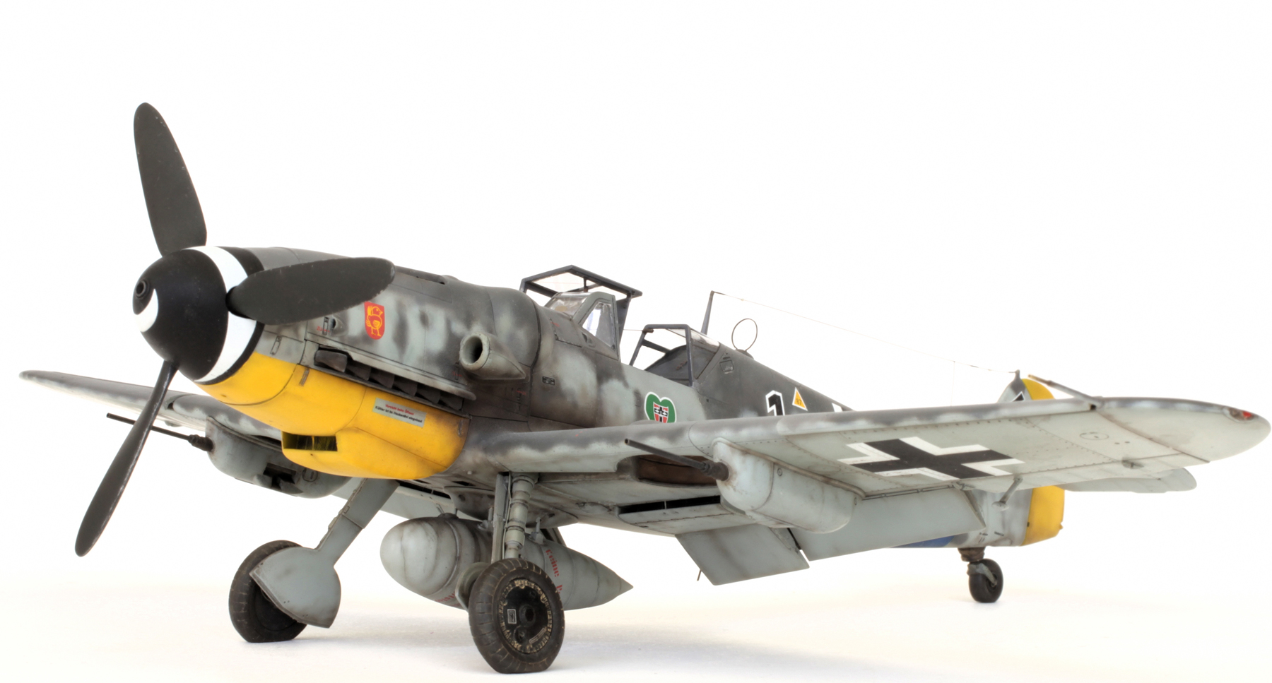
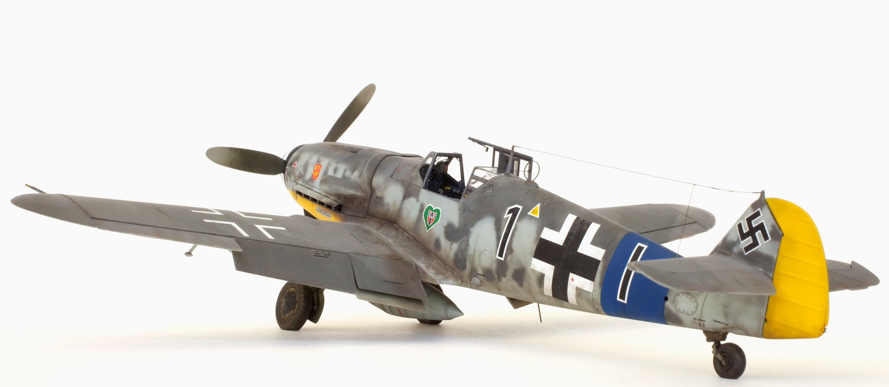
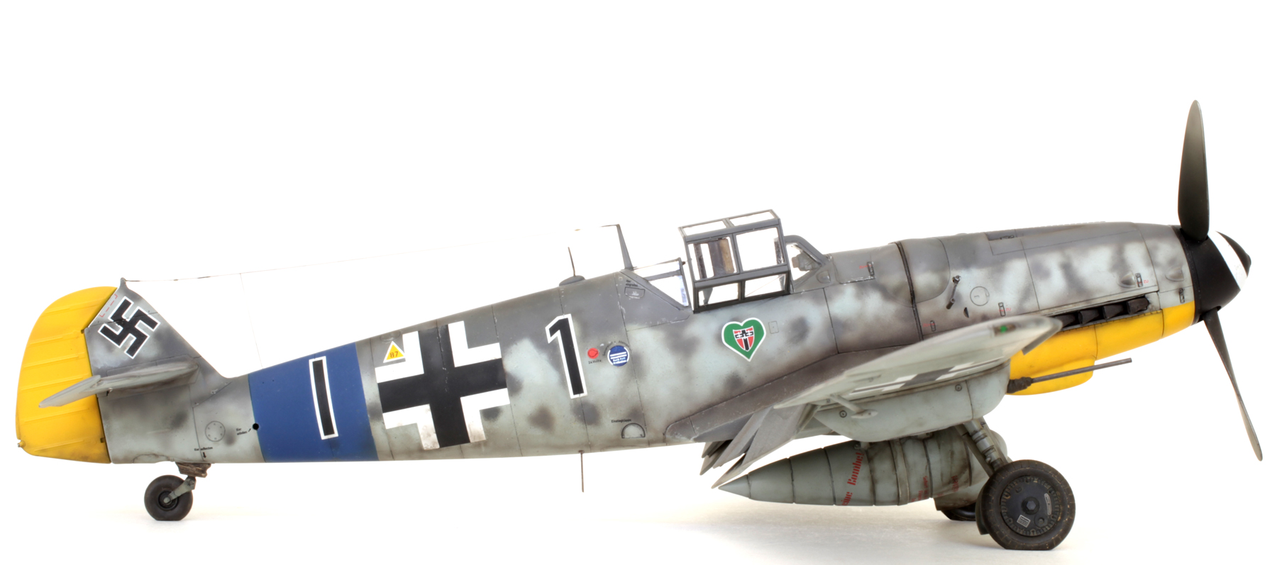
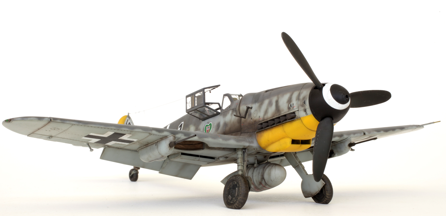
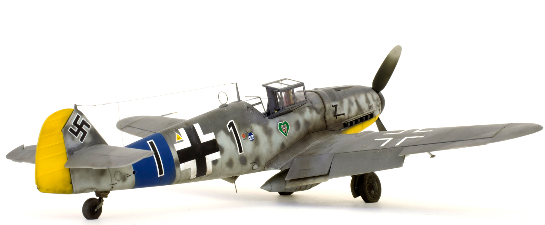
Tamiya 1/48 Messerscmitt Bf 109 G6

ME Bf 109 G6/R6 ‘Black 1’ W.Nr. Unknown 8./JG 54 Pilot Unknown Lüneburg, Germany Spring 1944.
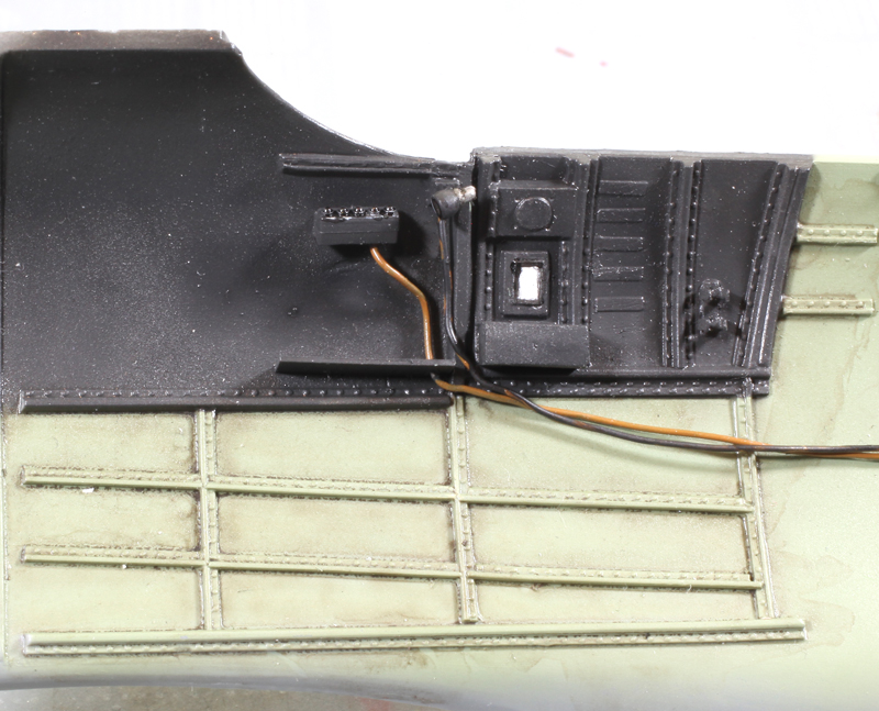
Starboard cockpit wall with some added detail to the oxygen supply mechanism.

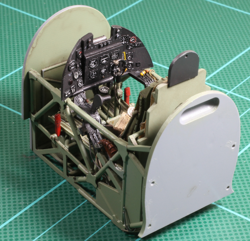
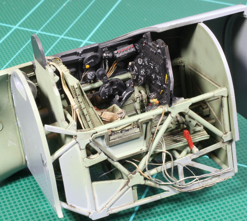
Cockpit tub with straps added to the rudder pedals and scratch-built seat belts added to the seat.
Bottom of the engine with extra detail.

Extra plumbing and wiring was added to the engine sides and bottom using fine copper and solder wire.

Underwing gondola cannon barrels were replaced with brass tube.
Kit decals were used for the instrument panel.

Wing radiator innards.

The navigation lights are moulded as part of the solid grey wing tips, so with some good photographic reference I painted them to look transparent.

I was very happy with the result.
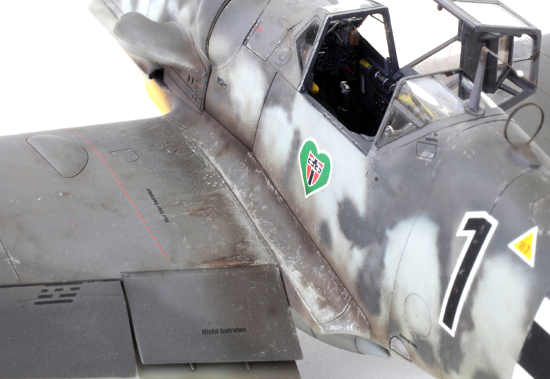
Chipping along the wing roots was done using a very sharp Prismacolor silver pencil. Also in this shot can be seen grab handles on the rear frame of the forward canopy, retaining wire holding the centre canopy section and the replacement D/F loop made using scrap P/E.

Very dirty belly of this well-used machine.

The top deck’s pretty messy too.
GALLERY


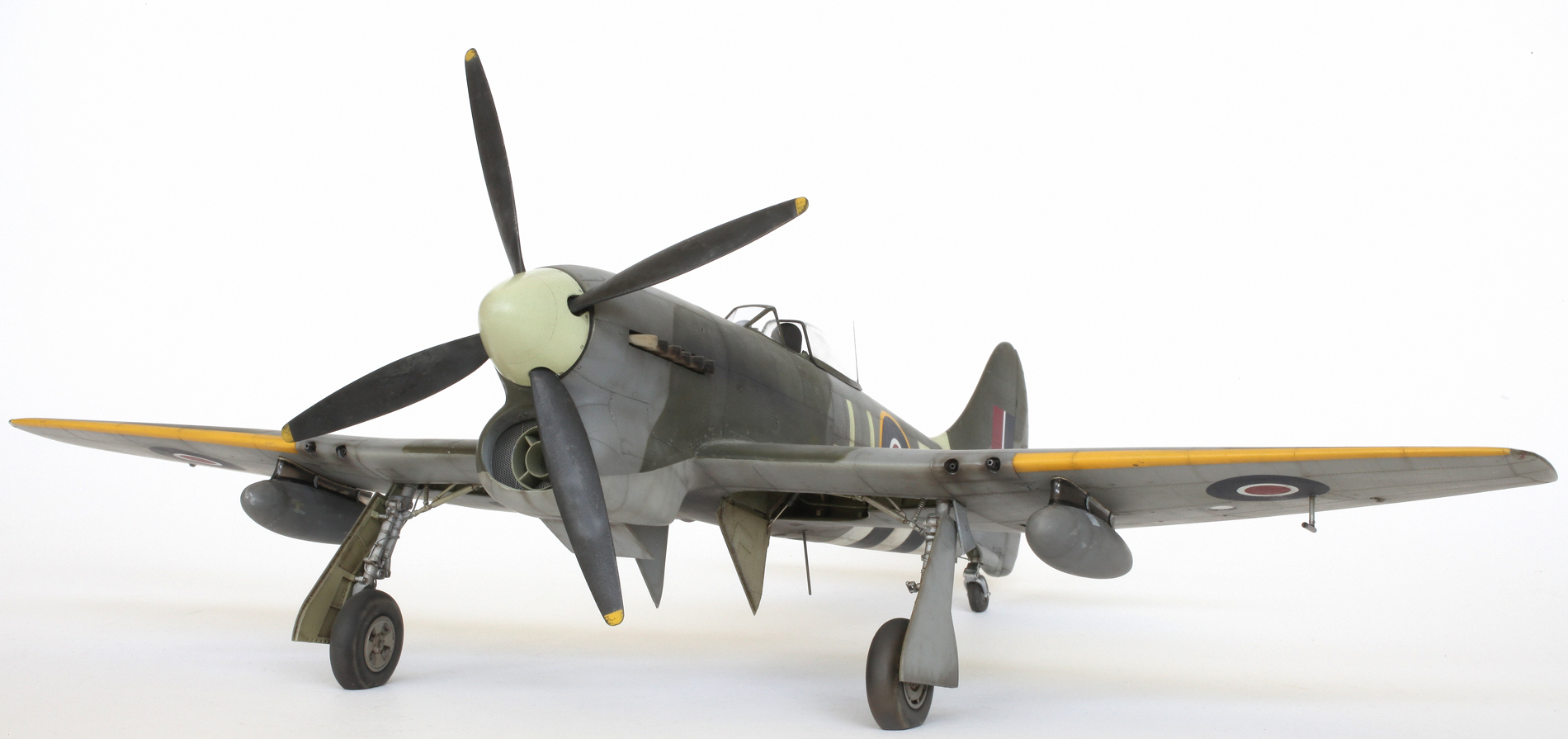
Special Hobby 1/32 Hawker Tempest Mk.V

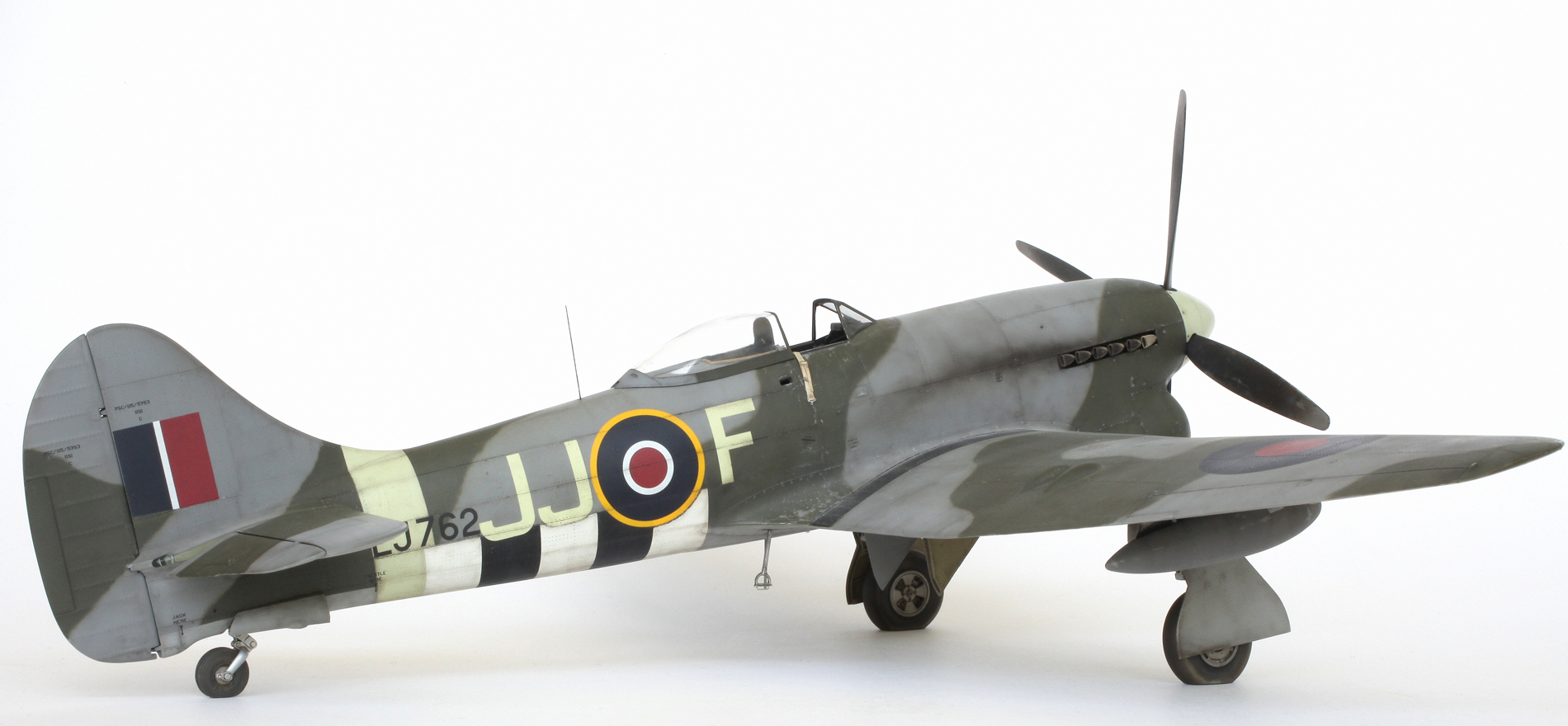
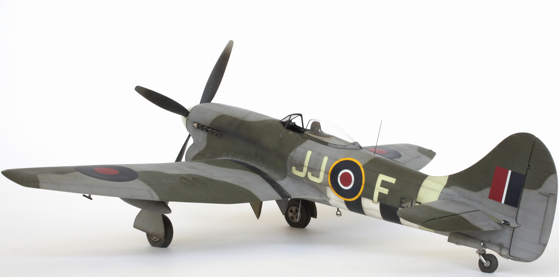
Hawker Tempest Mk.V EJ762/JJ-F of 274 Squadron, piloted by Flt. Lt. D. C. Fairbanks, DFC and Two Bars with 12.5 victories, while flying out of Volkel in Holland, October 1944.

Cockpit parts with some wiring and other detail added prior to painting. Front and rear engine radiators are also included in this shot.

Port cockpit sidewall with a little extra detail and a lot of wiring added.

Painted and weathered.
Starboard cockpit sidewall painted with not so much added detail.

Instrument panel with kit decal dials which have been cut out and added individually.

Seat painted and weathered with the kit-supplied HGW harnesses. The armoured headrest is much too thick and was later replaced with a more accurate, thinner and taller scratch built item.

Cockpit elements complete and waiting for assembly.
Assembled and waiting to be installed.
Installed. To my surprise and relief, the fit was very good.
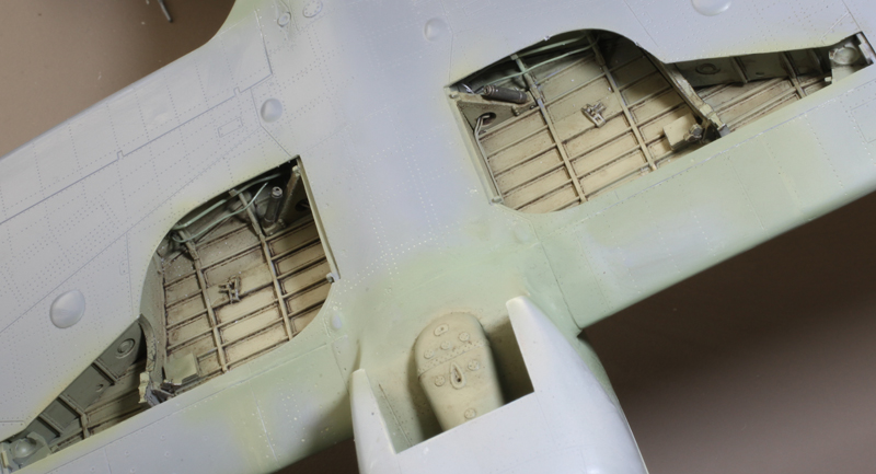
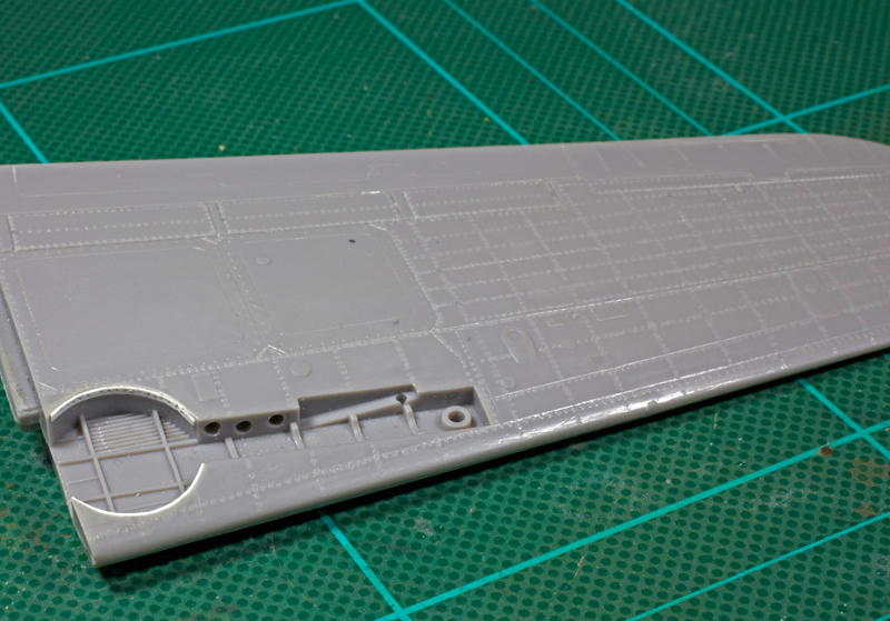
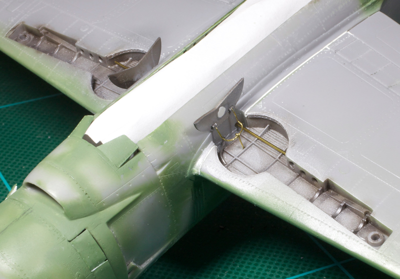
A little bit of extra plumbing was added to the wheel wells. There should be a lot more but I did not have enough reference of this feature to do an accurate job.
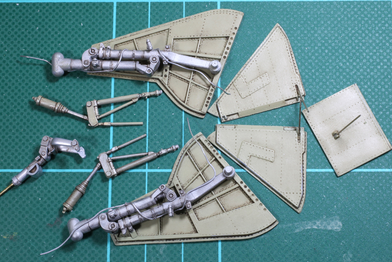
Undercarriage parts and radiator flap painted, weathered and detailed. There are quite a few more parts for the main gear that are not included in this shot but can be seen in later shots of the completed model. These, along with any other dangly bits, will all be installed when the model has been completed.

Upper surface camouflage has begun. If you look closely you can just see the very light pencil line indicating the colour demarcation and the letter ‘G’ for green in the appropriate areas.

Basic painting complete. Next step is weathering.

With me weathering always starts on the undersurfaces. As seen previously, the undercarriage doors and radiator flap were painted and weathered separately.

Upper surface weathering comprises exhaust staining, panel line shading, paint chipping and very subtle shading along the edges of any hard edge painted lines.This includes fuselage band, invasion stripes and wing walk strips. Paint chipping was achieved using a silver Prismicolor pencil. Also keen eyes may notice that the kit nose and spinner have been replaced with the much more accurate Barracuda resin parts.

Weathering complete. Decals next.
GALLERY


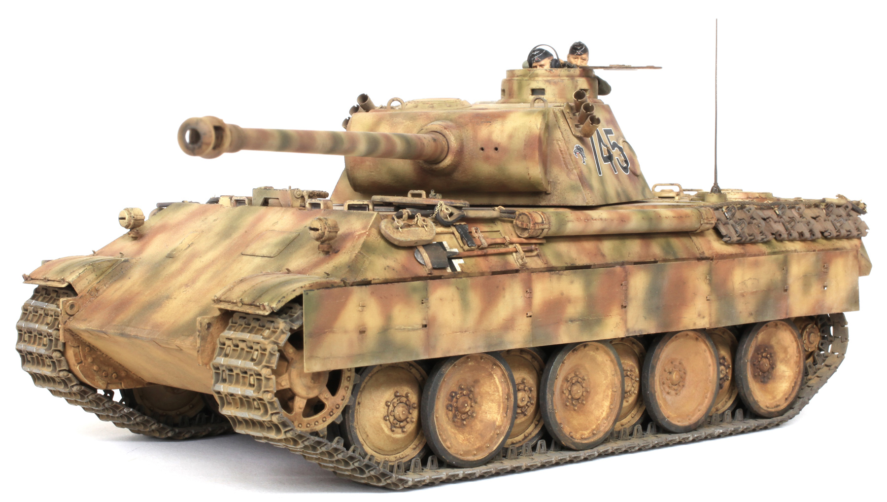
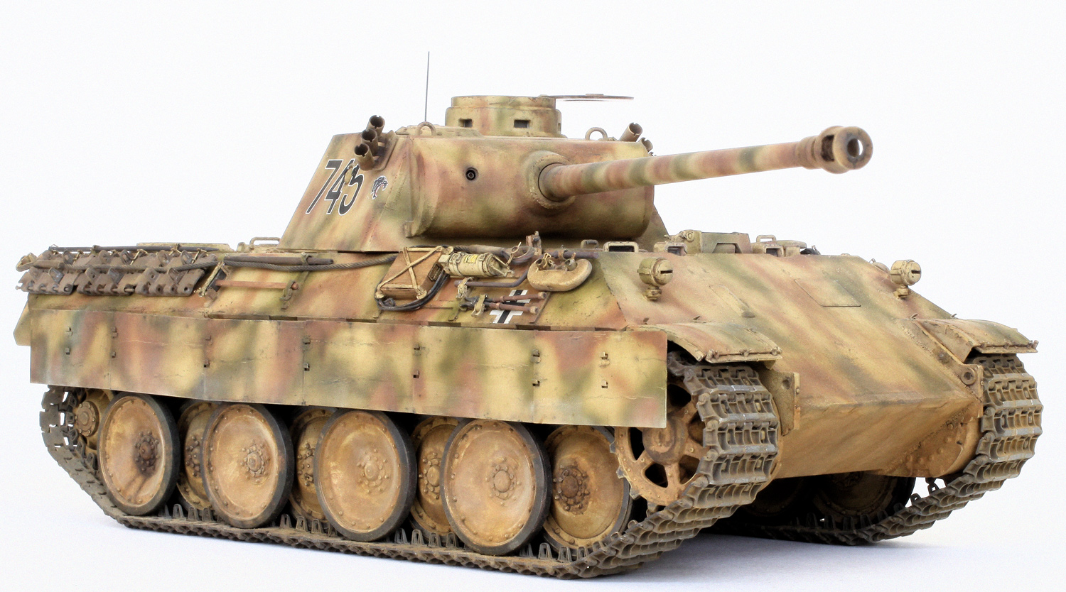
Tamiya 1/35 Panther Ausf.D

Tank No.745, 7th Company, 52nd Panzer Battalion, 39th Panzer Regiment, Kursk, July 1943
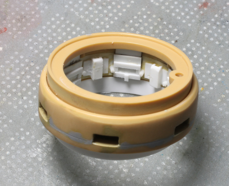
First order of business was to add some detail to the rather sparse interior of the kit commander’s cupola and after hours of searching the net I could not find any clear reference for this feature. The closest I could find were some interior photos and illustrations of Bovington’s early Tiger 1 which has a similar dustbin type cupola. Using these pics as my reference I added the detail you see here using plastic card and rod. It’s not 100% accurate but it looks a lot better than nothing. Of course since completing the model I did find some good pics of the Panther D’s turret interior and surprisingly my effort is pretty close!
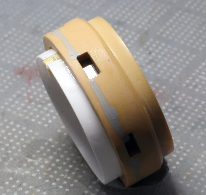
Lenses cut from clear acetate were glued to the inside of the periscope openings before the other interior detail was added.
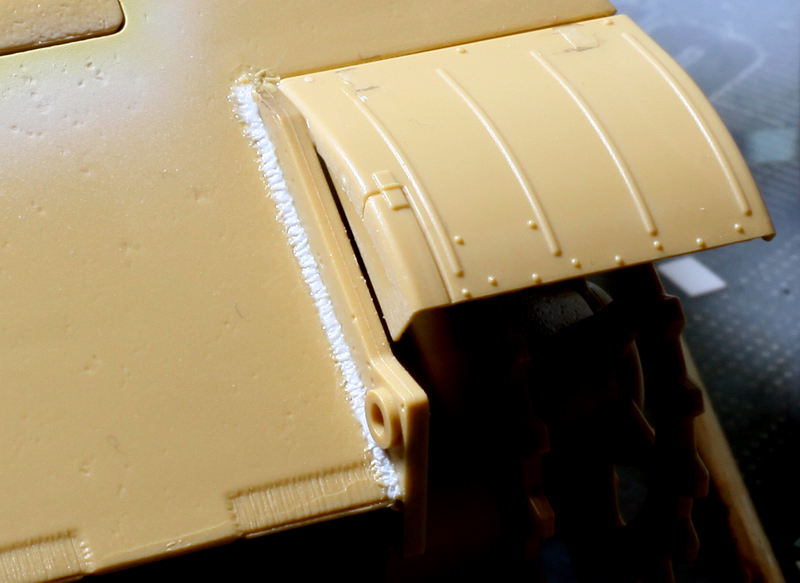
Missing weld beads were added using lengths of Evergreen plastic rod and stretched sprue. Once glued in place these were drenched with Tamiya extra thin liquid cement to soften them up. They were then shaped using the point of a needle mounted in a pin vice. Existing weld beads were also beefed up using the same method.
The kit’s smoke grenade launcher brackets were replaced with finer items made from .020 thou plastic card. In this shot you can also see some of the existing weld beads which have been given some extra body.
Plumbing for the launchers was added using brass tube and fine wire.
Model Point 90mm Nb.k.wg smoke/grenade throwers (empty), item number 3551-1 were used to replace the kit parts.

Launcher wiring connected.

The turned brass MG 34 muzzle from Aber’s update set 35 L-184 was used in the absence of any kit offering for the turret mounted coaxial machine gun.
The same Aber update set as the MG 34 also includes a turned aluminium KwK 42 L/75 gun barrel and eight piece turned brass and P/E muzzle brake.
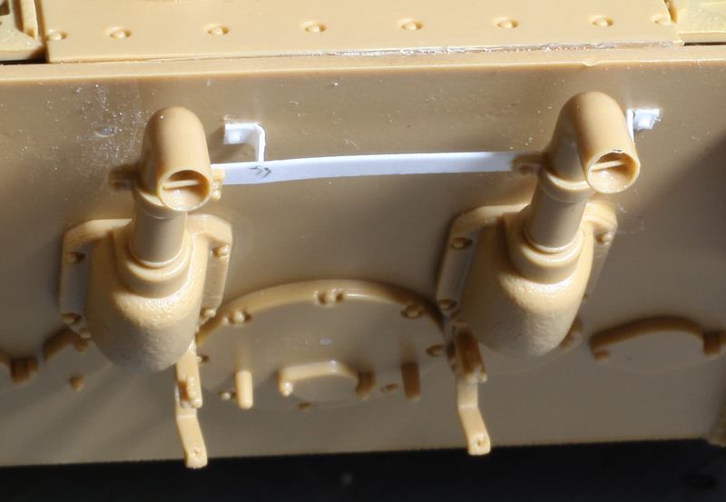
A new support bracket for the exhaust pipes was made using Evergreen plastic strip to replace the heavy looking kit part. The bracing rod in the open end of each pipe was added using stretched sprue.
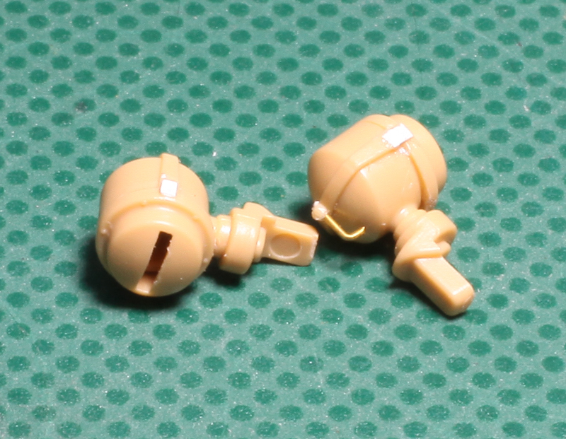
The handle on the back of each headlight cover bracket was added using brass wire.
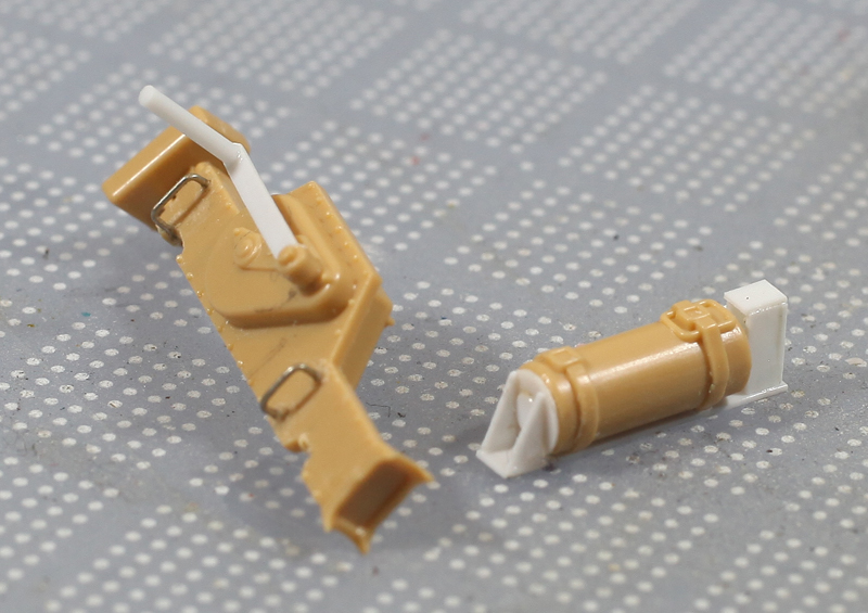
Extra detail was added to the jack and fire extinguisher using plastic card, plastic rod and brass wire.

Even though I didn’t use the metal gun barrel from Tamiya’s Detail-Up set, I did use the plastic parts for detailing the turret interior. These include the rear end of the coax MG 34, the binocular main gun sight and the breach for the main gun (above). As these parts may be glimpsed through open turret hatches, they received a quick paint job.

Kit external tool racks were used with the addition of some extra detail in the way of Aber’s workable P/E clamps and clasps.

Left side tool rack with extras.

The hull and turret with most extras added, these include the P/E Grille Set 12666 from Tamiya, most of the bits from the very fragile Gum Ka P/E set T-07 and lots of plastic and brass wire bits from me. The whole thing has been given a coat of red primer.

Most of the external stowage painted, weathered and ready to be attached.

Road wheels, drive sprockets and idler wheels have all been painted and weathered prior to installation.

With the finished running gear in place, the WWII Productions resin individual track link sets were cleaned up, assembled and painted before being very carefully installed. These tracks are workable but the click together joining system is inherently weak and during installation several breaks did occur. Very annoying and very time consuming to repair. I don’t think I will be using them again. Also in this shot you can see along the bottom edge of the upper hull that I have used plastic strip to beef up the attachment points for the P/E hangers and side skirts from Armorscale. These will replace the overly thick plastic kit parts.

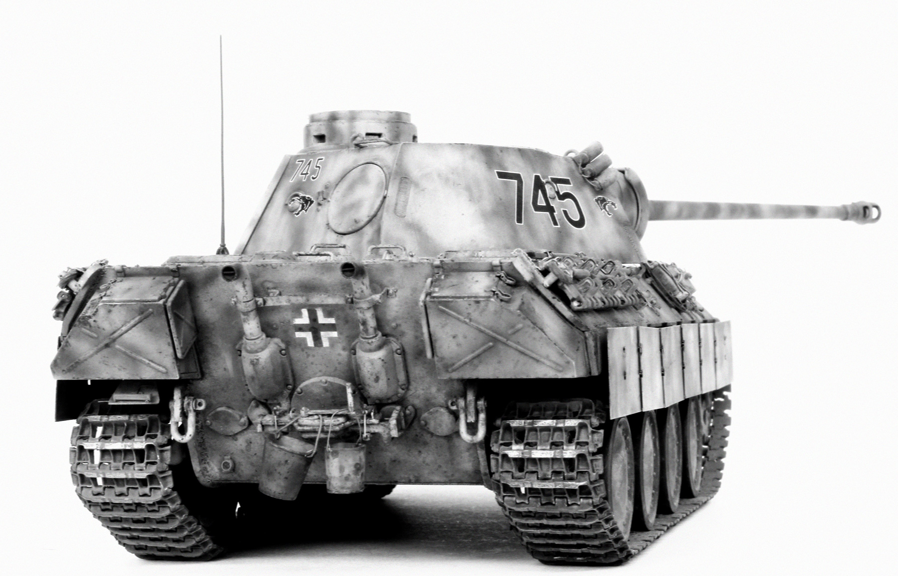
The completed model showing the Armorscale side skirts painted and hung. Also in this shot can be seen Tamiya’s P/E grille set and brass radio antenna from Adlers Nest. Securing the tow cables, spare track links and tow hooks are lots of P/E chains and pins from Gum Ka. The bucket hanging from the jack handle was found in the spares box while the straight-sided can next to it was scratch built from plastic card and wire. The exposed hinge teeth of the the spare track links were drilled and pins made from brass wire were selectively inserted.

I don’t normally add figures to my models but these guys looked much better than Tamiya’s usual offering so with a bit of extra detail added here they are. I’m not really happy with my effort but I suppose they do add an element of life and a sense of scale.
GALLERY